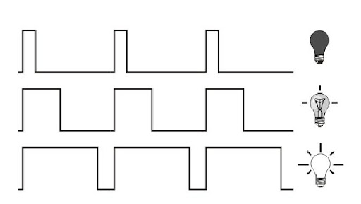
The goal: To adjust the LED brightness using the PWM module.
What we have: PIC16f628a and devboard + proteus.
First, take a look at the bd of PWM from pic mikroe resource (yup, I loved their pictures at that moment)
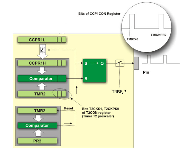
The period of PWM is defined by the PR2 register: when TMR2 will count up to the PR2 value, we will get a logic high at the S of the SR latch, so the latch output will be also logic high. Simultaneously, the timer will be reset.
At the same time, the data in CCPR1L + 2 bits CCP1X, CCP1Y are copied to the register CCPR1H, when timer TMR2 is reaching this value it generates a reset condition for SR latch, so output goes low. Simple and nice.
Let me try some base setup, we need to know two basic equations:
PWM period = (PR2 + 1)⋅4⋅Tosc⋅TMR2_precaller_value
Pulse width = (CCPR1L:CCP1CON<5:4>)⋅Tosc ⋅ TMR2_precaller_value
There is a very detailed routine in the datasheet, I just write it down here as well.
1. Set the period of PWM by PR2 register value.
2. The duty cycle value– register CCPR1L and CCP1CON<5:4>
3. RB3 set as an output pin
4. Set TMR2 prescaler value and enable timer
OK, now some real actions should happen
First of all, we need to define the specs we want to achieve:
- PWM frequency – 2 KHz
- The duty cycle can be adjusted 8 times (from 0 to 100%)
- The adjustment is realized by clicking the switches
To get such a frequency we should write to PR2 number 124d (the TMR2 prescaler is 4).
For example lets calculate a value of CCPR1L:CCP1CON<5:4> for 50% duty cycle (50% from 500 = 250) :
250u = 4*0.25u*x => x = 250 => CCPR1L = 0b00111110, CCP1X = 1, CCP1Y = 0
That’s it! no more boring calculations, here is my code:
#include

#define _XTAL_FREQ 4000000


__CONFIG(WDTDIS & UNPROTECT & MCLREN & LVPDIS & HS);


void pwm() {

unsigned char x = 0;

unsigned char state = 1;


while (state) {

if (!RB0) {

 __delay_ms(100);

 if (!RB0) {

 if (x > 0) { x--;} else x = 0;

 }

}


if (!RB1) {

 __delay_ms(100);

 if (!RB1) {

 if (x < 8) { x++;} else x = 8;

 }
}

if (!RB2) {
 __delay_ms(100);
 if (!RB2) {
 state = 0;
 INTF = 0;
 }
}

switch (x) {
case 0:                     // 0%
 CCPR1L = 0;
 CCP1X = 0;
 CCP1Y = 0;  break;
case 1:                     // 12.5%
 CCPR1L = 0b00001111;
 CCP1X = 1;
 CCP1Y = 0;  break;
case 2:                     // 25%
 CCPR1L = 0b00011111;
 CCP1X = 0;
 CCP1Y = 0;  break;
case 3:                     // 37.5%
 CCPR1L = 0b00101110;
 CCP1X = 1;
 CCP1Y = 1;  break;
case 4:                     // 50%
 CCPR1L = 0b00111110;
 CCP1X = 0;
 CCP1Y = 1;  break;
case 5:                     // 62.5%
 CCPR1L = 0b01001110;
 CCP1X = 0;
 CCP1Y = 0;  break;
case 6:                     // 75%
 CCPR1L = 0b01011101;
 CCP1X = 1;
 CCP1Y = 0;  break;
case 7:                     // 87.5%
 CCPR1L = 0b01101101;
 CCP1X = 0;
 CCP1Y = 1;  break;
case 8:                     // 100%
 CCPR1L = 0b011111100;
 CCP1X = 1;
 CCP1Y = 1;  break;

}

}
}

void main() {

PORTB = 0;
TRISB = 0b00000111;
PR2 = 0b01111100;

CCPR1L = 0;                               // default is 0%
CCP1X = 0;
CCP1Y = 0;

CCP1M3 = 1;                               // enabling pwm
CCP1M2 = 1;
T2CKPS0 = 1; T2CKPS1 = 0;                 // prescaler is 4
TMR2ON = 1;                               // tmr2 is on

GIE = 1;
INTE = 1;

for (;;) {
 // endless cycle
}

}

void interrupt isr() {                    // interrupt on RB0
if (INTF) {
pwm();
}
}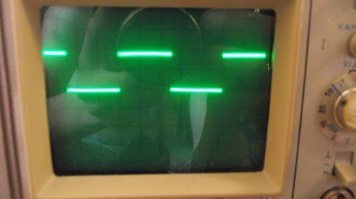
The scope screenshot with 50% duty cycle (1 square = 1 ms) The video with the LED :)