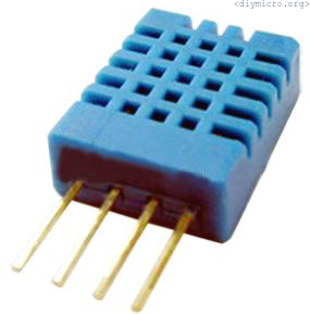
I was developing a small DIY project where the humidity should be controlled, the microcontroller for the brain is our good old friend – pic16f628a.
Starting as usual from the datasheet reading.
The typical specs looks like this:
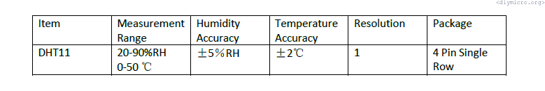
Roughly speaking – I am not impressed at all, I should have rather bought DHT22 sensor, but we have what we have.
Getting the application diagram from the datasheet as well:
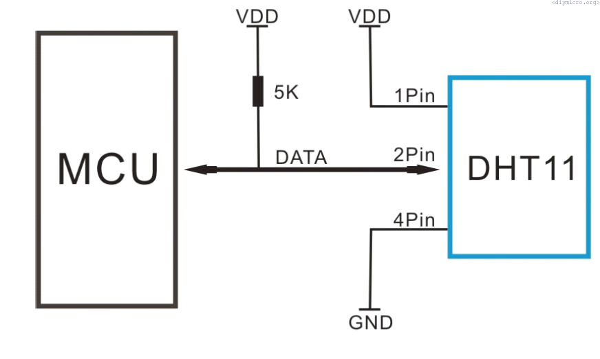
A manufacturer suggests to use the pull-up 5KOhm resistor if the cable has the length shorter than 20 meters. If the cable is longer than this there are no clear instructions 🙂 The transfer initiation should look like this:
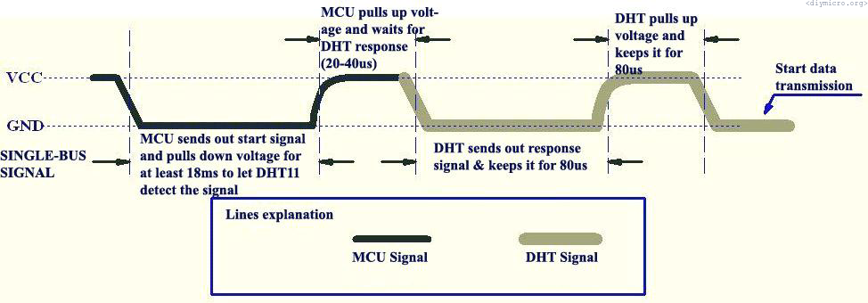
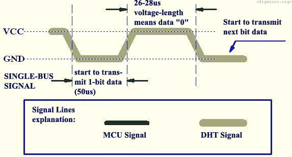
The uC pulling the line to the ground for at least 18ms, then pulling to the vdd and change the IO direction to the input, the time for sensor to respond. This is how “0” from the sensor looks like:
And the logical “1”:
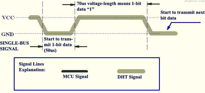
The difference between 1 and 0 is just a different pulse duration, let do some practice now:
#include

#define _XTAL_FREQ 12000000
#define State TRISB0
#define HumPin RB0

__CONFIG(WDTDIS & UNPROTECT & LVPDIS & HS);

unsigned char DHTbyte[5];

void main() {

State = 1;
CMCON = 0x07;

PEIE = 1;
INTEDG = 0;                 \\Работаем по спадающему фронту
HumPin = 1;                 \\Подтягиваем линию к питанию

for (;;)
{
if (!RB1)
  {
    __delay_ms(100); \\Антидребезг
    State = 1;
    State = 0;
    HumPin = 0;             \\Проваливаем линию
    __delay_ms(20);         \\Ждем около 20мс
    State = 1;
    HumPin = 1;             \\Подтягиваем к питанию
    __delay_us(40);         \\Ждем 40мкс
    State = 1;

  }//if
}//while(1)

}//main
I had to use higher oscillator frequency since DHT11 requires higher than 1MHz cycle time, so I used 12MHz just because it was available in my stashes.
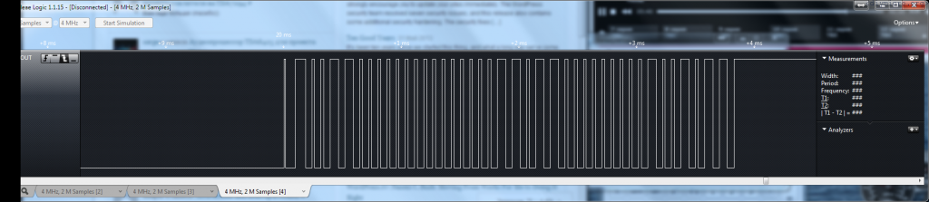
If you look carefully you will see first pull-downs from uC, then the 0 -> 1 combination with 80us pulse duration. In the end the sensor holds the line at the ground level for 50us. The data package has a next structure: total 5 bytes, the first byte is the humidity value, then empty byte, then the temperature, the empty byte, the control sum byte. Those empty bytes are most likely here since DHT11 and DHT22 have the same protocol, but DHT22 has a better accuracy. Now we have the main information, all we need to do is to decide how 1 and 0 will be decoded in the uC:
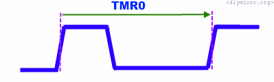
By each rising edge we will capture timer value and restart it: if the value is higher than 80us, than we have 1, if no – 0. Sounds simple in theory, but practically I got issues – my timer count value was equal to 1.33us, but the debug showed me that logical one duration was about 63.84us, not 80us. Probably I again got a surprise from aliexpress… Whatever, I can live with it, adjusting the code to actual values:
void GetRHandTemp()
{
   INTE = 0;                //Вырубаем прерывания по RB0
   DHTbyte[0] = 0;          //Байт для влажности
   DHTbyte[1] = 0;          //Байт для температуры
   DHTbyte[2] = 0;          //Байт для контрольной суммы
   Humflag = 0;
   IsrCount = 0;            //Со старта обнуляем количество прерываний
   State = 1;               //Проваливаем линию на 20 мс
   State = 0;
   HumPin = 0;
   __delay_ms(20);
   State = 1;
   HumPin = 1;
   __delay_us(40);
   State = 1;
   INTEDG = 0;              //Прерывания по спадающему фронту
   INTE = 1;

while (!Humflag)
{

  if (InteFlag)
     {
      INTE = 0;
      if (IsrCount==2) INTEDG = 1;         //После двух срабатываний меняем направление на противоположное
      if ((IsrCount > 2) && (IsrCount < 12)) //Байт влажности
         {
          DHTbyte[0]<<=1;
          if (tempTmr0>50) DHTbyte[0] |= 0b00000001;
          InitTimer0();
         }

      if ((IsrCount > 18) && (IsrCount < 28))      //Байт температуры
         {
          DHTbyte[1]<<=1;
          if (tempTmr0>50) DHTbyte[1] |= 0b00000001;
          InitTimer0();
         }

      if ((IsrCount > 34) && (IsrCount < 44))     //Контрольная сумма
         {
          DHTbyte[2]<<=1;
          if (tempTmr0>50) DHTbyte[2] |= 0b00000001;
          InitTimer0();
         }

 InteFlag = 0;
 INTE = 1;
 }//if (InteFlag)

 if (IsrCount>=43)                 //Все нужные фронты пойманы
 {
   Humflag = 1;                    //Условие выхода из цикла
   INTE = 0;
   lcd_clear();
   lcd_goto(0x00);
   lcd_puts("RH");
   lcd_goto(0x06);
   lcd_puts("Temp");
   display_digit(DHTbyte[0],0x40);  //выводим влажность на экран
   display_digit(DHTbyte[1],0x46);  //выводим температуры
   lcd_goto(0x48);
   lcd_putch(0b11011111); //градус
   lcd_putch(0b01000011); //С
   lcd_goto(0x0E);
   if (DHTbyte[2] == (DHTbyte[0]+DHTbyte[1]))
      lcd_puts("ok");                //если контрольная сумма совпала
    else
       lcd_puts("er");               //если не совпала
} //if (IsrCount>=43)
 }
}
Time to test:

Looks like a working device!
Pingback: Pic Lab, PIC18, Experiment #2, DHT22 | diymicro.org