Task: To study the possibility of using of the DIY touch capacitive sensor on the pcb
Tools: PIC18f1230, a pcb with exposed square copper areas
So long story short, my cheap amazon lamp did not survive for a long time, but I really did like the LED light it gave. In the article below I will describe how to use a copper pad and the pic microcontroller without much additional circuitry.

OK, so I bought the PIC18f1230 uC during a chip shortage time and the chip was among the cheapest available, which had both the adc and the pwm channels – it was my main requirement for this small project.
Time to dig the datasheet a little bit and check what we can get out of this ADC:
Chold = 25pF, max R of the buffer is 2.5KOhm. The datasheet says that such a configuration requires at least 2.4us to settle properly. Now let’s look what is the maximum sample rate we can get out this uC:

It’s pretty much obvious that we don’t have a super-duper ADC here. 2.86MHz is the max + 2.4us for the acquisition, even if don’t need any extra time we will end up with 2.4us + 10*0.35us = 5.9us, which gives about 170 Ks/s maximum sampling rate. Yup, not the greatest for sure.
Initially, I was thinking about adding the quartz crystal with the hope to speed up the adc, but there is nothing to speed up, we are already on a quite slow horse. So, the internal oscillator will serve more than well, since it can operate up to 8MHz. And this is what I have chosen – the uC is configured to work at 8MHz.
Having the info mentioned above in mind, there is a configuration we would use:
void InitADC()
{
	//Initialiation of the ADC module
	VCFG0 = 0; //VDD is a reference
	//Configure the Tad to 8Tosc (for Fosc=8MHz) - 1us
	ADCS2 = 0;
	ADCS1 = 0;
	ADCS0 = 1;
	//Configure the acqusition time (should be more than 2.5us for 2.5Kohm source), with 1us we could make 2us or 4us
	ACQT2 = 0;
	ACQT1 = 1;
	ACQT0 = 0;

	ADON = 1;
	ADIE = 1;
	ADIF = 0;
}
The acquisition time is settled to be 4us to satisfy the requirements and Tad is 8Tosc = 1us. The whole conversion cycle is going to take 15 Tad or 15us, even worse than expected 🙂
Unfortunately, the chip also doesn’t have an internal reference voltage generator so we could use the external (if we will see the need for it) or try to build the workaround with VDD being used as a reference voltage, which leads to a pretty large LSB (5V/1024 = 4.88mV). But let’s start and see how things will be shaping out. The last bad thing – the uC has just 4:1 mux for adc channel, not like 10 sadly, so if there is a requirement for more sensors, it is questionable how reliable you can do this (and by what methodology).
Now, we have a piece of the copper connected to the ADC, plus we know (supposedly) how to work with the ADC and what should we do next? First of all, read the appnote AN1298, it describes how any input without an additional circuitry can be used literally with any fast enough ADC.
The equivalent circuit when ADC is connected to the input looks like this:
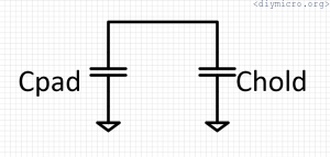
Initially, Chold is precharged to VDD and Cpad is completely discharged, when they are connected the charge redistribution happens and we have the next equation:
V_x = C_{hold}VDD/C_{pad}Cpad is normally larger than Chold, so you will have the fraction of VDD voltage at the input, also, when the pad is touched or the finger is close to the pad, the pad capacitance is increasing making the resulting voltage even smaller. I could measure the pad capacitance and check if the equation holds, but with given slowness of the ADC and leakage currents inside this not quite meaningful exercise, we would rather just check what kind of waveforms we are getting from our pcb and will try to work with them (an experimental approach).
The suggested routine inside of the document:
Sensing Steps
To perform the sensing, do the following:
- Drive secondary channel to VDD as a digital
output. - Point ADC to the secondary VDD pin (charges
CHOLD to VDD). - Ground sensor line.
- Turn sensor line as input (TRISx = 1).
- Point ADC to sensor channel (voltage divider
from the sensor to CHOLD). - Begin ADC conversion.
- Reading is in ADRESH:ADRESL
I made for simplicity functions which sets channel as analog input or as digital one/zero:
void adcAN2analogIn()
{
	PCFG2 = 0;
	TRISA4 = 1;
}

void adcAN2digitalOne()
{
	//Make AN2 channel digital output 1
		PCFG2 = 1;
		TRISA4 = 0;
		PORTAbits.RA4 = 1;
}

void adcAN2digitalZero()
{
	//Make AN2 channel digital output 1
		PCFG2 = 1;
		TRISA4 = 0;
		PORTAbits.RA4 = 0;
}
Now we can combine everything together and check the waveform.
In order to see on the scope what is happening I’ve made a program:
void main()
{
//INTOSC TO 8MHz
 IRCF2 = 1;
 IRCF1 = 1;
 IRCF0 = 1;
 SCS1 = 1;
//INTOSC setup

 //trying uart
 InitUart();
 writeDataUart((char *) "\r\ndiymicro.org\r\n");

 adcAN0digitalOne();
 adcAN1digitalOne();            //an1 to 1
 adcAN2digitalZero();           //an2 to 0
 adcSelChan(1);                 //charge Chold to vdd

 T0CS = 0;
 T016BIT = 1;
 PSA = 0;
 T0PS2 = 0;
 T0PS1 = 1;
 T0PS0 = 0;
 TMR0ON = 1;
 TMR0IF = 0;
 TMR0IE = 0;

 InitADC();
 ADIE = 0;


 IPEN = 1;
 GIE = 1;
 PEIE = 1;

 while(1)
 {
    if (rx_data_recieved)  //some data recieved
    {
        writeByteUart(rx_data_recieved);
        while(BusyUSART());

        rx_data_recieved = 0;
    }


 }//while(1)

}//main()


void __interrupt(high_priority) HighIsr(void)
{
    if (RCIF)
    {
       rx_data_recieved = ReadUart();
    }

    if (TMR0IF)
    {
             adcSelChan(1);          //an1 to 1
             __delay_us(200);
             adcAN2digitalZero();           //an2 to 0

             adcAN2analogIn();
             adcSelChan(2);//
             TMR0 = 0;
             TMR0IF = 0;
             PORTAbits.RA0 = !PORTAbits.RA0;
    }

}
The scope was showing weird stuff:
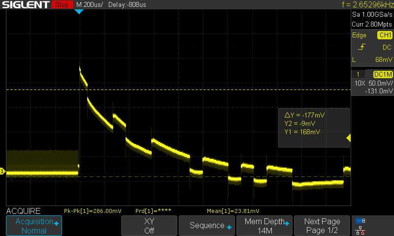
This is not what I expected – left untouched sensor, right side the sensor with a finger on it. It behaves rather as usual RC discharge, not as a capacitive divider. Plus levels are near the ground which is not great with my ADC, since there is no reference and VDD equals to 5V. Yes, not great at all, maybe this happens due to the adc slowness, or maybe internal switches have huge leakage or extremely long rise/fall times, and the charge redistribution happens in the middle switching point.
Next, I just made the sensor cap precharged to the vdd instead of the ground and put it on a constant loop:
if (TMR0IF)
{
adcAN2digitalOne();
adcSelChan(2);
adcAN2analogIn();
TMR0 = 0;
TMR0IF = 0;
PORTAbits.RA0 = !PORTAbits.RA0;
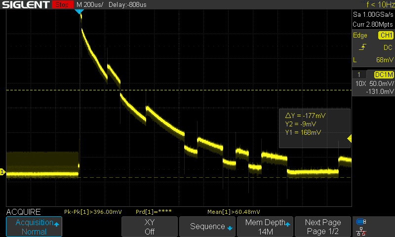
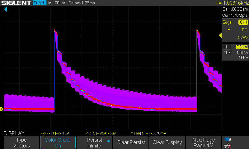
}In this case, we should operate with the whole 5V range and the leakage will not be this substantial:

The visible line is showing the case without the finger and all the purple stuff happens when the finger is touching the pad. With 5V reference, it’s going to be much easier to digitize this curve and check if a couple of values higher than this bare line then most likely somebody placed the finger on it.
The first thing now is to gather the reference line and save it in the program code, so we will know at least what is normal and what is different from the normal.
This was done with help of the timer but let’s make now the adc counts 32 samples:
if (!adc_conversion_start)
{
ADIE = 1;
ADON = 1;
adcAN2digitalOne();
adcSelChan(2);
adcAN2analogIn();
samples_count = 0;
adc_conversion_start = 1;
GO = 1;
}
if (adc_conversion_ended)
{
if (samples_count<32)
{
adc_data[i] = (ADRESH << 2) | (ADRESL>>6);
samples_count++;
GO = 1;
}
if (samples_count>=32)
{
GO = 0;
ADON = 0;
ADIE = 0;
adc_conversion_ended = 0;
adc_conversion_start = 0;
}
adc_conversion_ended = 0;
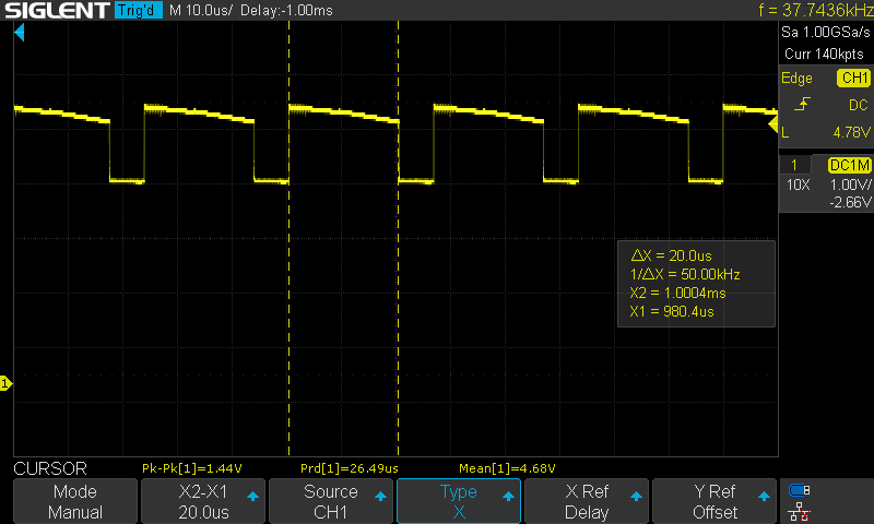
}My estimate of ADC the required time for a whole conversion was 15us, so 15*32 = 0.48ms, but what I had gotten from the scope surprised me a lot:
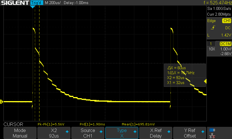
1.9ms !!! It is 4 times larger than the estimate, why?
So I know for sure that Fosc is 8MHz, since I saw the Fosc/4 at the test output. After this I had checked the TMR0 timing: Fosc/4 period is 0.5us, with a prescaler equal to 8 we have one timer step equal to 4us. 4us * 256 = 1024 – and that is exactly what I had seen on the scope. Now, why the heck the ADC gathering the data four times more than calculated…
I made a simple program which is settling the AN2 channel to 1 and then digitizing it. It shows 30us in the interrupt routine time (more then 15us but still), but then it becomes 56us when the ADC data register is transferred to the int variable like this:
adc_data[i] = (ADRESH << 2) | (ADRESL>>6);
This is suggesting that we used 1 freaking period to read the single bit, wow.
Continue experimenting I found that if I move the whole procedure to the interrupt function, remove extra handlers in the main function, change the data variable to two char instead of the single int and avoid the usage of << >> operators the total period becomes 26us, from which 6us is a time interval during which variables are loaded, so my adc gathering now is 20us and initial part of it – settling of the vdd level – ok, now at least I can be calm, the datasheet and reality finally matched.
As soon as we added some post-processing of the data – the time of one sample is increased again, up to 30us:
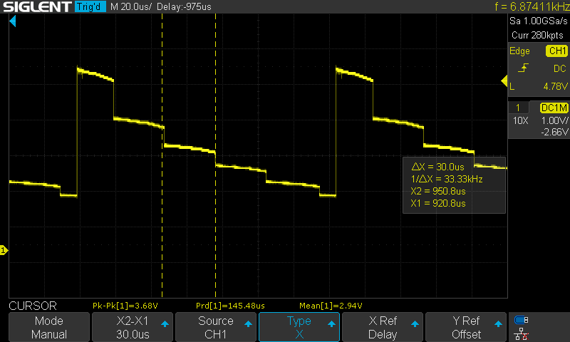
So for the polling time in 1ms we still need about 32 steps:
void __interrupt(high_priority) HighISR(void)
{
    if (ADIF)
    {
        if (!samples_count)
        {
             adcAN2digitalOne();
             adcAN2analogIn();
             samples_count++;
             GO = 1;

        }else
        {
          temp1 = ADRESH;
          temp2 = ADRESL;
          if (samples_count>=31)
          {
              samples_count=0;
              GO = 1;
          }else
          {
              samples_count++;
              GO = 1;
          }

        }
    ADIF = 0;
    }

}
OK, this part is resolved, we can move forward.
Now it’s time to return the post-processing back to the main cycle, it’s not fun to work with arrays inside of the interrupt routine.
When I had moved the whole piece of code to the main cycle (using flag variables of course), the total time became 1.22ms. The sampling time now is 38us (+8us).
Introducing of array out of 2×32 chars increases the time up to 1.4ms (43.75 us per sample), getting worse and worse yup.
void main()
{
//INTOSC TO 8MHz
 IRCF2 = 1;
 IRCF1 = 1;
 IRCF0 = 1;
 SCS1 = 1;
//INTOSC setup

 InitUart();
 writeDataUart((char *) "\r\ndiymicro.org\r\n");
 InitADC();
 ADIE = 1;


 IPEN = 0;
 GIE = 1;
 PEIE = 1;
 adcSelChan(2);
 adcAN2digitalOne();
 adcAN2analogIn();
 GO = 1;
 samples_count = 0;

 while(1)
 {


 }//while(1)

}//main()


void __interrupt(high_priority) HighISR(void)
{
    if (ADIF)
    {
        temp1[samples_count] = ADRESH;
        temp2[samples_count] = ADRESL;


          if (samples_count>=31)
          {
              writeDataUart((char *) "\033c");
              writeDataUart((char *) "Printing the data from ADC\r\n");

              for(i=0;i<32;i++)
              {
                writeDataUart((char *) "\r\n");
                adc_data_temp = temp1[i];
                adc_data_temp = (adc_data_temp<<8) | temp2[i];
                NumToUart(adc_data_temp);
              }
             __delay_ms(200);__delay_ms(200);__delay_ms(200);__delay_ms(200);__delay_ms(200);
              samples_count=0;
              adcAN2digitalOne();
              adcAN2analogIn();
              GO = 1;
          }else
          {
              samples_count++;
              GO = 1;
          }


        ADIF = 0;
    }

    if (RCIF)
    {
       rx_data_recieved = ReadUart();
    }

}
This code gives us the “untouched” curve profile:

Now what we need to do can be represented with such a routine:
- Start the timer for a polling interval
- Set the adc channel to 1
- Change it to the analog input and start the digitization in cycle for 32 times
- Get the adc reading and compare it to the saved constant array + delta_y, if it is larger add + 1 to the trigger touch value
- After all 32 conversions are concluded, check the touch trigger value, if it larger than some value – the touch sensor is being touched, if smaller – meh, some mistake has happened
Based on the data from the adc, the constant array has been created:
const int untouched_sensor[32] = {1005,700,548,431,339,266,209,164,129,101,79,62,48,37,28,22,16,12,9,7,5,4,2,1,1,0,0,0,0,0,0,0};
const char delta_y = 30;
delta_y variable is used for calibration for a certain sensor and adjusting the sensitivity. By experiments I had determined that a “good” polling time is about 500ms, it is good enough to debounce a false touching, the code is shown below:
void main()
{
//INTOSC TO 8MHz
 IRCF2 = 1;
 IRCF1 = 1;
 IRCF0 = 1;
 SCS1 = 1;
//INTOSC setup

 InitUart();
 writeDataUart((char *) "\r\ndiymicro.org\r\n");
 InitADC();
 ADIE = 0;

//launching the timer for polling (~0.5s)
 T0CS = 0;
 T016BIT = 0;
 PSA = 0;
 T0PS2 = 0;
 T0PS1 = 1;
 T0PS0 = 1;
 TMR0ON = 1;
 TMR0IF = 0;
 TMR0IE = 1;
//end of timer configuration


 IPEN = 0;
 GIE = 1;
 PEIE = 1;

 samples_count = 0;

 while(1)
 {
    if (timer0_event)       //time to check if sensor has been touched
    {
        TMR0IE = 0;
        TMR0ON = 0;
        timer0_event = 0;
        ADIE = 1;
        adcSelChan(2);
        adcAN2digitalOne();
        adcAN2analogIn();
        GO = 1;
    }

    //adc conversion ended, analizing outputs and restarting timer
    if (adc_conversion_ended)
    {
        ADIE = 0;
        adc_conversion_ended = 0;
        x = 0;

              for(i=0;i<32;i++)
              {
                adc_data_temp = temp1[i];
                adc_data_temp = (adc_data_temp<<8) | temp2[i];
                if (adc_data_temp>(untouched_sensor[i]+delta_y))
                    x++;
              }

        if (x>=touch_trigger)       //sensor touched event is detected
        {
            writeDataUart((char *) "\r\nSensor is touched!\r\n");
            NumToUart(touch_counter);
            touch_counter++;
        }


        TMR0IE = 1;
        TMR0ON = 1;
    }
    //end of postprocessing the adc data

 }//while(1)

}//main()


void __interrupt(high_priority) HighISR(void)
{
    if (ADIF)
    {
        temp1[samples_count] = ADRESH;
        temp2[samples_count] = ADRESL;


          if (samples_count>=31)
          {
              samples_count=0;
              adc_conversion_ended = 1;
          }else
          {
              samples_count++;
              GO = 1;
          }


        ADIF = 0;
    }

    if (RCIF)
    {
       rx_data_recieved = ReadUart();
    }

    if (TMR0IF)
    {
        adcAN2digitalOne();
        adcAN2analogIn();
        timer0_event = 1;
        TMR0IF = 0;
    }

}
The result looks like this:
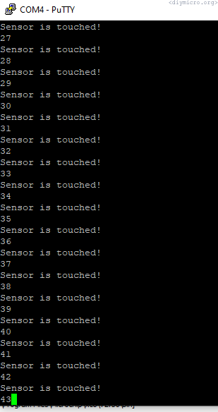
Works pretty solid, although keep in mind that this method works well only when you really touch the copper. The capacitive divider method should work much better even without direct contact, but it requires (I guess) faster adc, and I would use it with some voltage reference generator available + with smaller vdd.
The next question I had – is it possible to use the single channel and distinguish between a number of connected sensors to this channel? I connected the single sensor through 3 resistors: 3, 9 and 18 KOhms and launched the similar procedure to see how the picture will look like on the scope:

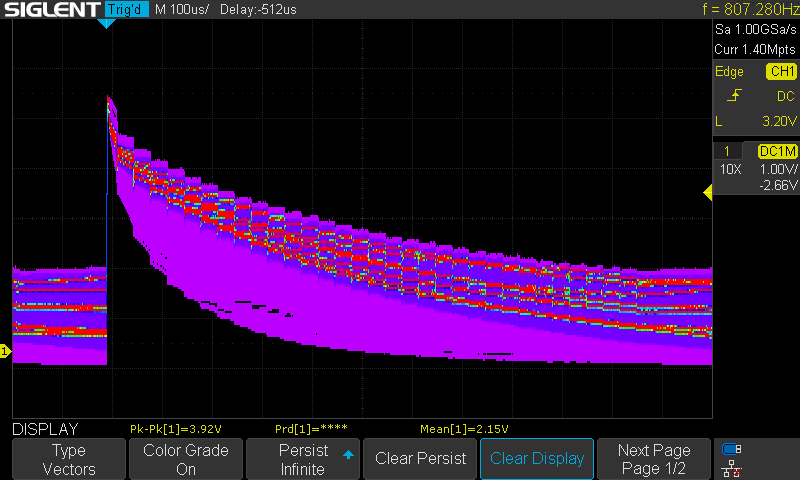
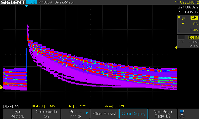
This appeared to be not quite useful, all I can say is that I see the difference in the first couple cycles and that’s it, better to try to push numbers into uart.
Well, doesn’t look promising at all. But maybe there are some repeating patterns which are can be determined. Need to create some averaging tool which then clearly will show them…
Averaging should be good for us and maybe it will reveal some hidden issues:
if (adc_conversion_ended)
{
ADIE = 0;
adc_conversion_ended = 0;
if (touch_counter>=32)
{
touch_counter = 0;
writeDataUart((char *) "\033c");
writeDataUart((char *) "Printing the data from ADC\r\n");
}
writeDataUart((char *) "\r\n - ");
NumToUart(touch_counter);
writeDataUart((char *) " - ");
for(i=0;i<32;i++)
{
adc_data_temp = temp1[i];
adc_data_temp = (adc_data_temp<<8) | temp2[i];
NumToUart(adc_data_temp);
writeDataUart((char *) " ");
}
touch_counter++;
TMR0IE = 1;
TMR0ON = 1;
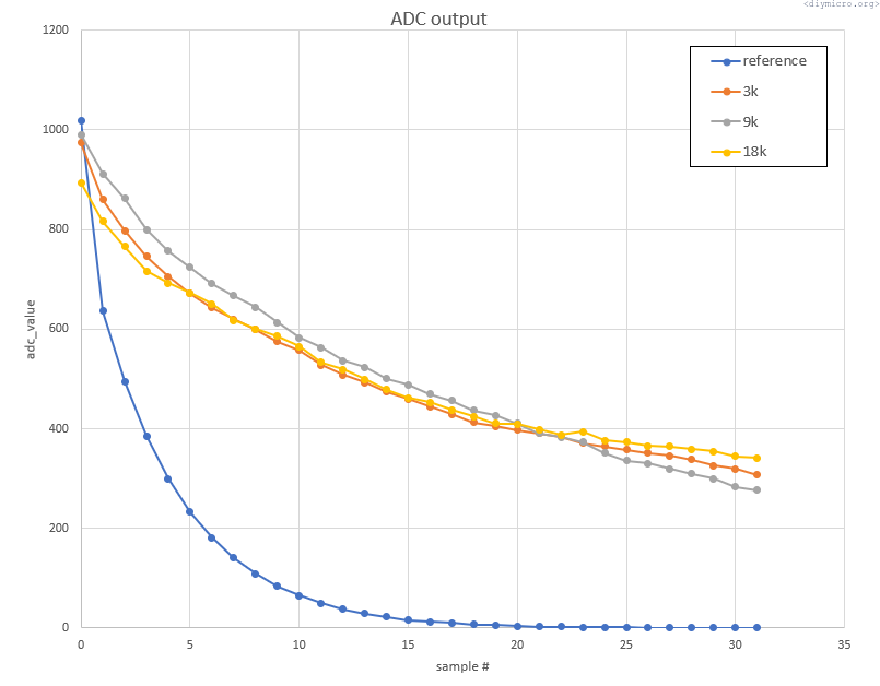
}Now I have a terminal window flooded with numbers which then can be post-processed then in excel.
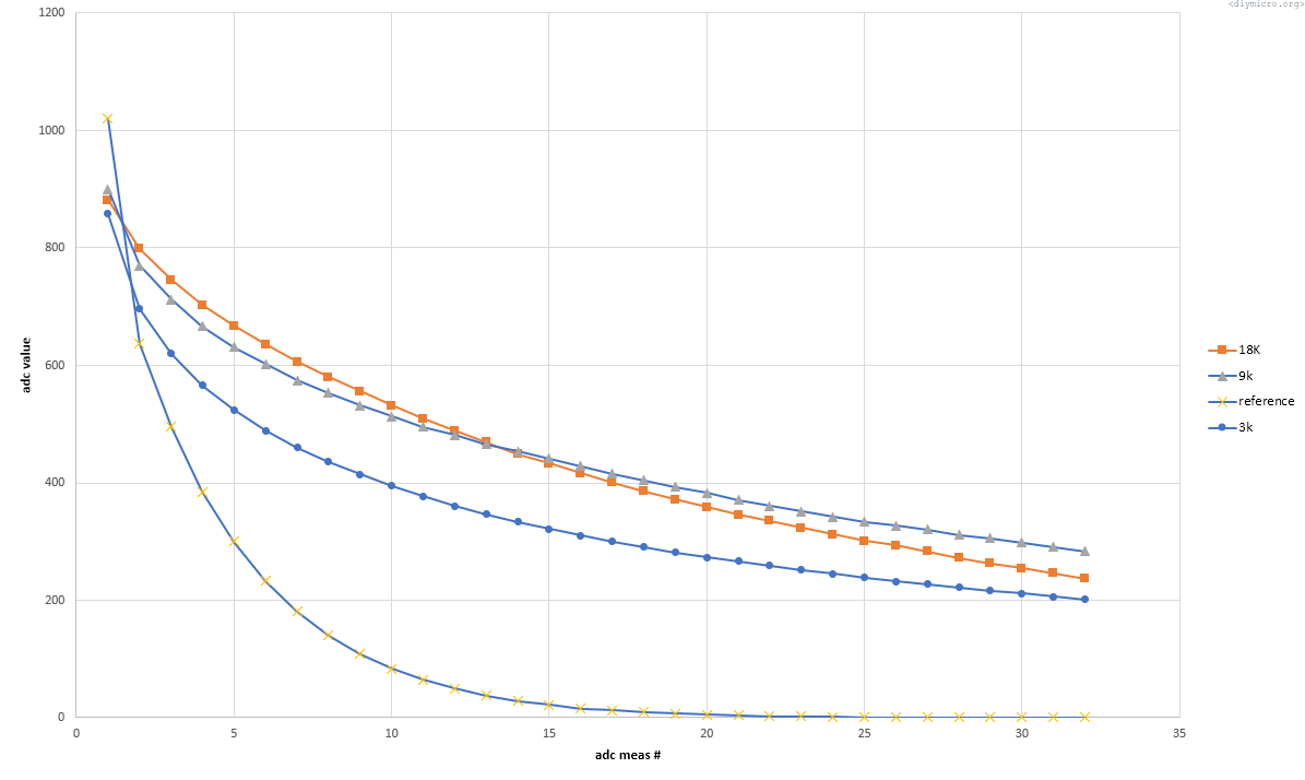
Now looks a bit more clear I would say. 3K can be distinguished from others, but 9 and 18K look similar, perhaps we need to increase the difference between positions…
500, 3 and 18K:
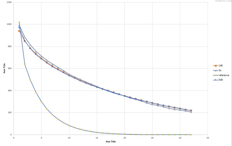
Even worse.
3, 9 and 50K:

3K, 220K and 50K:
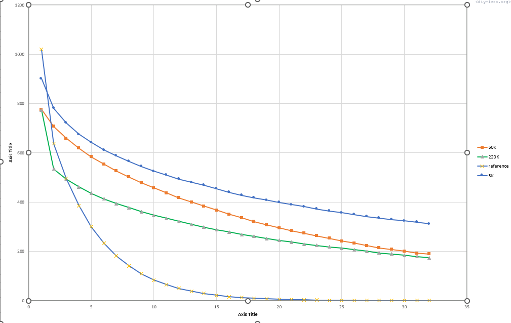
Already something, but can we maybe push somehow 50K to the better difference.
At that moment an idea struck my head: what will happen if I put a 100pF cap instead of 50K res:
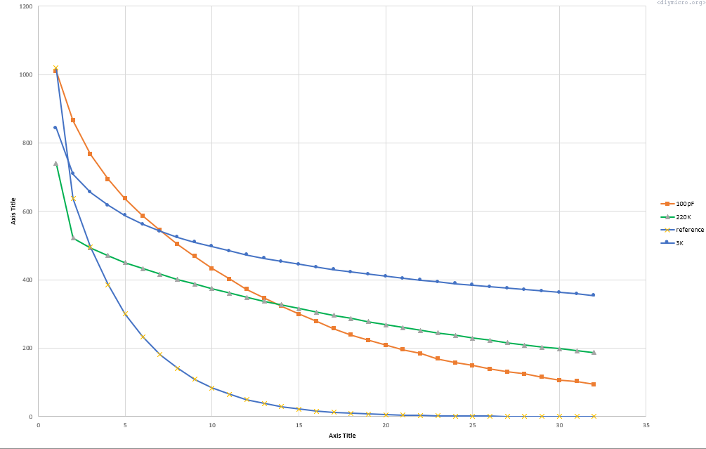
The behavior changed a bit, what If I put 12pF, 27pF and 100pF capacitors instead of all resistors.
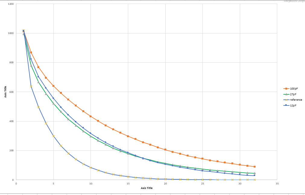
The main advantage – a repeatability is much better than for a resistor. After a couple of iterations I got this:
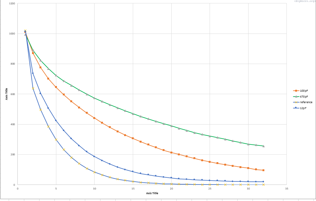
So these are averaged curves, but where are the margins?
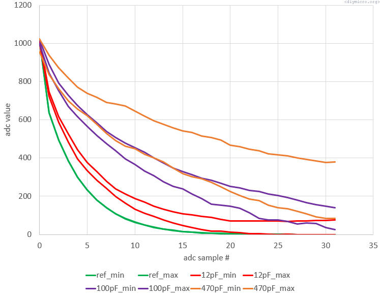
A bit of overlapping, but not bad at all, not bad. If I plot resistors margins, it a complete disaster:
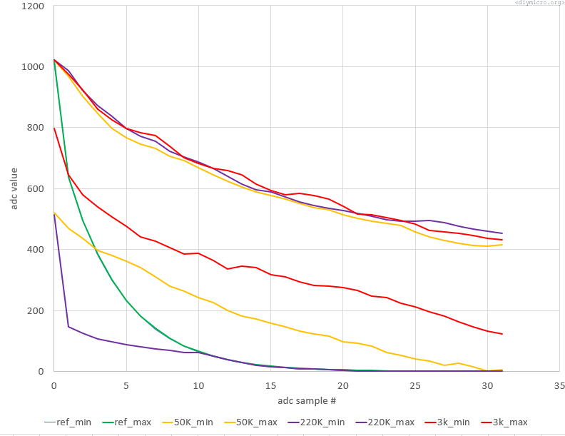
There are no chances, to make it work reliably. Capacitors on the other hand with a pinch of experimental back and forth could work more or less reliably, with a hand tuning probably for every single board and every single sensor. Enough of the talking, here is a full code (w/o adc and uart setups, though)
#include <xc.h>
#include "uart.h"
#include "adc.h"

#define _XTAL_FREQ 8000000 //The speed of your internal(or)external oscillator


// PIC18F1230 Configuration Bit Settings

// 'C' source line config statements

// CONFIG1H
#pragma config OSC = INTIO1     // Oscillator (Internal oscillator, port function on RA6 and RA7)
#pragma config FCMEN = OFF      // Fail-Safe Clock Monitor Enable bit (Fail-Safe Clock Monitor disabled)
#pragma config IESO = OFF       // Internal/External Oscillator Switchover bit (Oscillator Switchover mode disabled)

// CONFIG2L
#pragma config PWRT = OFF       // Power-up Timer Enable bit (PWRT disabled)
#pragma config BOR = BOHW       // Brown-out Reset Enable bits (Brown-out Reset enabled in hardware only (SBOREN is disabled))
#pragma config BORV = 3         // Brown-out Reset Voltage bits (Minimum setting)

// CONFIG2H
#pragma config WDT = OFF        // Watchdog Timer Enable bit (WDT disabled (control is placed on the SWDTEN bit))
#pragma config WDTPS = 32768    // Watchdog Timer Postscale Select bits (1:32768)

// CONFIG3L
#pragma config PWMPIN = OFF     // PWM Output Pins Reset State Control bit (PWM outputs disabled upon Reset)
#pragma config LPOL = HIGH      // Low-Side Transistors Polarity bit (Even PWM Output Polarity Control bit) (PWM0, PWM2 and PWM4 are active-high (default))
#pragma config HPOL = HIGH      // High Side Transistors Polarity bit (Odd PWM Output Polarity Control bit) (PWM1, PWM3 and PWM5 are active-high (default))

// CONFIG3H
#pragma config FLTAMX = RA5     // FLTA Mux bit (FLTA input is muxed onto RA5)
#pragma config T1OSCMX = LOW    // T1OSO/T1CKI MUX bit (T1OSO/T1CKI pin resides on RB2)
#pragma config MCLRE = ON       // Master Clear Enable bit (MCLR pin enabled, RA5 input pin disabled)

// CONFIG4L
#pragma config STVREN = ON      // Stack Overflow/Underflow Reset Enable bit (Reset on stack overflow/underflow enabled)
#pragma config BBSIZ = BB256    // Boot Block Size Select bits (256 Words (512 Bytes) Boot Block size)
#pragma config XINST = OFF      // Extended Instruction Set Enable bit (Instruction set extension and Indexed Addressing mode disabled)

// CONFIG5L
#pragma config CP0 = OFF        // Code Protection bit Block 0 (000400-0007FF) (Block 0 is not code-protected)
#pragma config CP1 = OFF        // Code Protection bit Block 1 (000800-000FFF) (Block 1 is not code-protected)

// CONFIG5H
#pragma config CPB = OFF        // Code Protection bit (Boot Block Memory Area) (Boot Block is not code-protected)
#pragma config CPD = OFF        // Code Protection bit (Data EEPROM) (Data EEPROM is not code-protected)

// CONFIG6L
#pragma config WRT0 = OFF       // Write Protection bit Block 0 (000400-0007FF) (Block 0 is not write-protected)
#pragma config WRT1 = OFF       // Write Protection bit Block 1 (000800-000FFF) (Block 1 is not write-protected)

// CONFIG6H
#pragma config WRTC = OFF       // Write Protection bit (Configuration Registers) (Configuration registers are not write-protected)
#pragma config WRTB = OFF       // Write Protection bit (Boot Block Memory Area) (Boot Block is not write-protected)
#pragma config WRTD = OFF       // Write Protection bit (Data EEPROM) (Data EEPROM is not write-protected)

// CONFIG7L
#pragma config EBTR0 = OFF      // Table Read Protection bit Block 0 (000400-0007FF) (Block 0 is not protected from table reads executed in other blocks)
#pragma config EBTR1 = OFF      // Table Read Protection bit Block 1 (000800-000FFF) (Block 1 is not protected from table reads executed in other blocks)

// CONFIG7H
#pragma config EBTRB = OFF      // Table Read Protection bit (Boot Block Memory Area) (Boot Block is not protected from table reads executed in other blocks)


char rx_data_recieved = 0;
char tx_data_temp = 0;
const int sensor_n1_min[32] = {1010, 723, 581, 481, 396, 326, 268, 217, 174, 146, 118, 90, 71, 58, 39, 29, 27, 19, 10, 5, 0, 0, 0, 0, 0, 0, 0, 0, 0, 0, 0, 0};
const int sensor_n1_max[32] = {1023, 742, 606, 511, 428, 362, 306, 264, 223, 189, 162, 139, 113, 103, 91, 78, 67, 59, 50, 45, 42, 37, 33, 29, 30, 27, 28, 30, 32, 29, 22, 30};
const int sensor_n2_min[32] = {996, 851, 742, 674, 603, 554, 497, 452, 397, 359, 329, 300, 268, 245, 210, 170, 153, 128, 105, 98, 85, 57, 52, 34, 13, 20, 13, 1, 0, 0, 0, 0};
const int sensor_n2_max[32] = {1023, 896, 811, 731, 689, 642, 597, 566, 537, 503, 473, 448, 425, 402, 379, 355, 338, 321, 306, 290, 275, 263, 247, 233, 229, 219, 217, 209, 201, 191, 193, 179};
const int sensor_n3_min[32] = {994, 862, 792, 738, 684, 629, 589, 554, 523, 483, 458, 432, 399, 360, 344, 314, 288, 276, 256, 226, 213, 198, 171, 168, 155, 131, 127, 110, 104, 108, 82, 75};
const int sensor_n3_max[32] = {1023, 958, 892, 831, 788, 755, 719, 706, 676, 648, 633, 603, 579, 573, 551, 526, 523, 500, 487, 473, 462, 454, 439, 427, 424, 408, 403, 396, 381, 374, 364, 360};
const char delta_y = 30;
const char touch_trigger = 17;
volatile __bit tmr0flag = 0;
char i = 0;
char x = 0;
char touch_counter = 0;
int adc_data_temp = 0;
volatile __bit adc_conversion_start = 0;
volatile __bit adc_conversion_ended = 0;
volatile __bit timer0_event = 0;
volatile char samples_count = 0;
volatile char temp1[32];
volatile char temp2[32];
__bit sensor_n1_pressed = 0;
__bit sensor_n2_pressed = 0;
__bit sensor_n3_pressed = 0;
char sensor_n1_touches = 0;
char sensor_n2_touches = 0;
char sensor_n3_touches = 0;

void main()
{
//INTOSC TO 8MHz
 IRCF2 = 1;
 IRCF1 = 1;
 IRCF0 = 1;
 SCS1 = 1;
//INTOSC setup

 InitUart();
 writeDataUart((char *) "\r\ndiymicro.org\r\n");
 InitADC();
 ADIE = 0;

//launching the timer for polling (~1s)
 T0CS = 0;
 T016BIT = 0;
 PSA = 0;
 T0PS2 = 0;
 T0PS1 = 1;
 T0PS0 = 1;
 TMR0ON = 1;
 TMR0IF = 0;
 TMR0IE = 1;
//end of timer configuration


 IPEN = 0;
 GIE = 1;
 PEIE = 1;
 //adcSelChan(2);
 //adcAN2digitalOne();
 //adcAN2analogIn();
 //GO = 1;
 samples_count = 0;
 adcAN1digitalOne();
 while(1)
 {
    if (timer0_event)       //time to check if sensor has been touched
    {
        TMR0IE = 0;
        TMR0ON = 0;
        timer0_event = 0;
        ADIE = 1;
        adcSelChan(0);
        adcAN0digitalOne();
        adcAN0analogIn();

        GO = 1;
    }

    //adc conversion ended, analizing outputs and restarting timer
    if (adc_conversion_ended)
    {
        ADIE = 0;
        adc_conversion_ended = 0;
        //zeroing all the service variables
        sensor_n1_pressed = 0;
        sensor_n2_pressed = 0;
        sensor_n3_pressed = 0;
        sensor_n1_touches = 0;
        sensor_n2_touches = 0;
        sensor_n3_touches = 0;

       x = 0;

              for(i=0;i<32;i++)
              {
                adc_data_temp = temp1[i];
                adc_data_temp = (adc_data_temp<<8) | temp2[i];
                if ((adc_data_temp>=sensor_n1_min[i])&&(adc_data_temp<=sensor_n1_max[i]))
                {
                     sensor_n1_touches++;
                }//sensor n1 if
                    else
                    {
                        if ((adc_data_temp>=sensor_n2_min[i])&&(adc_data_temp<=sensor_n2_max[i]))
                        {
                            sensor_n2_touches++;
                        }//if sensor n2
                            else
                            {
                                 if ((adc_data_temp>=sensor_n3_min[i])&&(adc_data_temp<=sensor_n3_max[i]))
                                    sensor_n3_touches++;
                            }//else 2
                    }//else 1

              } //for


         writeDataUart((char *) "\033c");
         writeDataUart((char *) "\r\nSummary\r\n");
         writeDataUart((char *) "\r\n n1\r\n");
         NumToUart(sensor_n1_touches);
         writeDataUart((char *) "\r\n n2\r\n");
         NumToUart(sensor_n2_touches);
         writeDataUart((char *) "\r\n n3\r\n");
         NumToUart(sensor_n3_touches);

        if (sensor_n1_touches>=touch_trigger)       //sensor touched event is detected
        {
            writeDataUart((char *) "\r\nSensor #1 is touched!\r\n");

        }//if #1
            else
            {
                  if (sensor_n2_touches>=touch_trigger)
                  {
                        writeDataUart((char *) "\r\nSensor #2 is touched!\r\n");

                  }//if 2
                  else
                  {
                        if (sensor_n3_touches>=touch_trigger)
                            writeDataUart((char *) "\r\nSensor #3 is touched!\r\n");


                  }//else 3
            }//else 1


        TMR0IE = 1;
        TMR0ON = 1;
    }
    //end of postprocessing the adc data

 }//while(1)

}//main()


void __interrupt(high_priority) HighISR(void)
{
    if (ADIF)
    {
        temp1[samples_count] = ADRESH;
        temp2[samples_count] = ADRESL;


          if (samples_count>=20)
          {
              /*writeDataUart((char *) "\033c");
              writeDataUart((char *) "Printing the data from ADC\r\n");

              for(i=0;i<32;i++)
              {
                writeDataUart((char *) "\r\n");
                adc_data_temp = temp1[i];
                adc_data_temp = (adc_data_temp<<8) | temp2[i];
                NumToUart(adc_data_temp);
              }
             __delay_ms(200);__delay_ms(200);__delay_ms(200);__delay_ms(200);__delay_ms(200);  */
              samples_count=0;
              adc_conversion_ended = 1;
              //adcAN2digitalOne();
              //adcAN2analogIn();
              //GO = 1;
          }else
          {
              samples_count++;
              GO = 1;
          }


        ADIF = 0;
    }

    if (RCIF)
    {
       rx_data_recieved = ReadUart();
    }

    if (TMR0IF)
    {
        //adcAN0digitalOne();
        //adcAN0analogIn();
        timer0_event = 1;
        TMR0IF = 0;
    }

}
And the result is in this short gif :
Well the gif doesn’t work on the wordpress but trust me it worked.
Now back to the ugly truth – after like 2 months I did not have a time to work on the project and returned back to it. Surprise, surprise it did not work anymore at. Well it worked – but constant arrays should be changed to make it work again, not quite a reliable thing. As a bottomline – I do not recommend to use this method, rather just try to have workaround with a single sensor if possible and stop on a single constant array and a larger delta, should be a way more flexible and simple.
The source code.