Below is the procedure of a PWM veriloga controller created in Verilog-A language (behavioral description language)
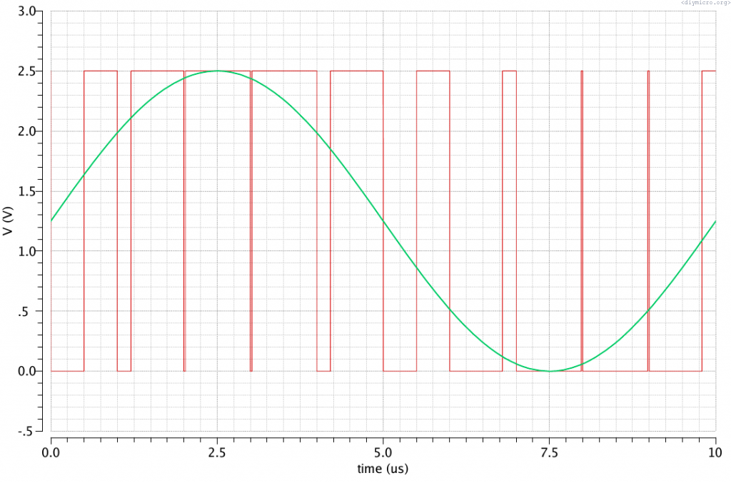
So, I need a PWM controller which is basically the block the duty cycle of which will vary in dependence of the control pin voltage. The previous picture shows the output of the controller (red) with input applied control voltage (green). The frequency is constant.
// VerilogA for TB_sarge, PWMController, veriloga

`include "constants.vams"
`include "disciplines.vams"

module PWMController(Clk, Duty, Out);
output Out;
input Clk;
input Duty;

electrical Clk;
electrical Out;
electrical Duty;

parameter real Vh = 2.5;          //Максимальное напряжение
parameter real Vl = 0;            //Минимальное напряжение
parameter real vth = (Vh+Vl)/2;   //Напряжение, при котором состояние будет переключаться
parameter real PWMperiod = 2.5u; //Период ШИМ
real state;                      //Переменная для обработки напряжения по входу Duty
integer n;                       //переменная индикатор состояния

real timeper;                    //характеристика скважности

analog begin
@(initial_step) state = 0;       //Инициализация

@(cross(V(Clk) - vth, +1)) begin //По каждому возрастающему фронту
  n = 1;
  timeper = $abstime;              //timeper = текущее время
  state = V(Duty);                 //state = напряжение на управляющем входе
end

@(timer(0, timeper+state*PWMperiod))     //таймер срабатывает через текущее время + часть периода шим
begin
 n = 0;                                 //и затягивает состояние выхода в противоположное
end

V(Out) <+ transition(n ? Vl:Vh, 0, 100p);  //выход равен либо Vh либо Vl, время нарастания 100 пс

end
endmodule
The controller is ready, now we can wire the clock source and the analog control voltage, but there is one thing to consider – the control input operates adequately only if input voltage range is from 0 to 1 V (0-100% duty cycle), that’s why I made also the voltage level converter:
// VerilogA for TB_sarge, PWMConverter, veriloga

`include "constants.vams"
`include "disciplines.vams"
module PWMConverter(In, Out);

input In;
output Out;
electrical In;
electrical Out;

parameter real VHpeak = 2.5;
parameter real VLpeak = 0;

analog begin
 V(Out) <+ (VHpeak - VLpeak -V(In))/(VHpeak-VLpeak);   //Разбиваем наш диапазон напряжений на 100 частей и получаем в итоге напряжение от 0 до 1

end
endmodule
In this code, beside of the conversion of the input control voltage I also made the inversion of it. If it is not desired then string #16 should be rewritten.
Now the testbench:
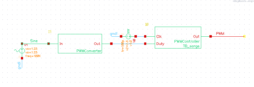
The result of a simulation is shown in the very first picture.