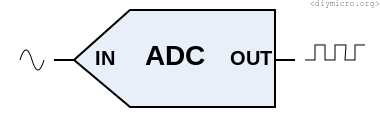
I was working on a small project where I needed to catch a certain button pressed event. Sounds simple initially, but I have 10 such buttons and it means that I need to have 10 IOs, or port expander, or make a digital matrix button handler (like 3×4 keypad) but these all variants are boring, I wanted something more interesting and make something like a DAC based on these buttons which will be digitazed by the built-in ADC in pic18f14k50. Thus, we will use a single port instead of 10, by cost of the more complicated code.
Let me start as usual – from reading of the datasheet.
There is a next story – we have 9 channels for a single ADC and 10 bit of resolution. Therefore, if we use 5V the LSB value about 5mV. This value is OK for me, in case if I would needed smaller LSB I could have used the different reference voltage for ADC and improved accuracy.

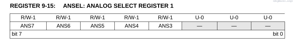
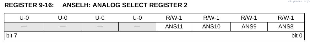
It is kind of obvious from the picture above – want to work with the ADC, set the ADON bit to 1. First thing to do is to configure ports properly – set TRIS of used pin to 1, set properly ANSEL and ANSELH registers (we’re going to use analog functions)
Then we need to choose a channel number in the ADCON0 register:
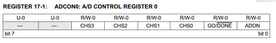
Possible configurations of the ADCON0 register are next:

Channels are kind of obvious, but two bottom options are curious. Curious they are but I am not going to explore it here, since I tried and did not get if I can get FVR internally or not (:
My pin choice is RC7, this is a channel number AN9, time to make some initial code:
 TRISC7 = 1;
 ANSEL = 0;                                                                   //here all analog buffers off
 ANSELH = 2;																  //turn on analog input for RC7(AN9)
 ADCON0 = 0b00100100;														  //Channel AN9 select
To set the reference levels we need to go to the register ADCON1:

I am OK with VDD and VSS, so I left the default values.
Then we have a story that we could set the averaging on a certain amount of ADC runs, but there is one peculiar thing – the interrupt bit will be set each single run and looks like there is no obvious indication when all runs are ended.
Next parameter worth to discuss is Tad – the conversion time per a single bit, to a full cycle we have to wait 11Tad:

The conversion time is adjusted by ADCS bits in ADCON2 register:
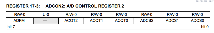
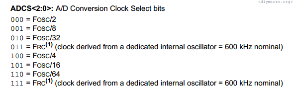
I have a 12 MHz quartz, nicely can divide on 4 only, so we are getting the ADC clock with ~3us period.
There is also ADFM bit, dedicated to alignment of bits, I like right side justification, so setting it to 1:
ADCON2 = 0b10000100; //Right justification, clock = Fosc/4
Now all we need to do is to enable ADC (ADON = 1) and launch the conversion (GO = 1), then, if we are not using interrupts, we can just wait till GO will be reseted to 0:
void main()
{

 TRISC7 = 1;
 ANSEL = 0;                                                                   //here all analog buffers off
 ANSELH = 2;																  //turn on analog input for RC7(AN9)
 ADCON0 = 0b00100100;														  //Channel AN9 select
 ADCON2 = 0b10000100;														  //Right justification, clock = Fosc/4
 ADON = 1;																	  //ADC is enabled!!!
 TRISB7 = 0; //TX pin set as output
 TRISB5 = 1; //RX pin set as input

 Vmeas = 0;

 UARTConfig = USART_TX_INT_OFF & USART_RX_INT_OFF & USART_ASYNCH_MODE & USART_EIGHT_BIT & USART_BRGH_HIGH ;    //прерывания выключены, асинхронный режим, 8 бит, высокоскоростной режим
 baud = 77;                 //Focs/(9600*16) - 1
 OpenUSART(UARTConfig,baud);


 putsUSART( (char *) "Welcome to Diymicro.ru\r\n" );
 GO = 1;																	   //go, go, go!!! (:

 while(GO){};
 Vmeas = (ADRESH << 8) | ADRESL;
 NumToUart(Vmeas);

 while(1){};

}
I have applied 2.3V to the input and that what I’ve got:
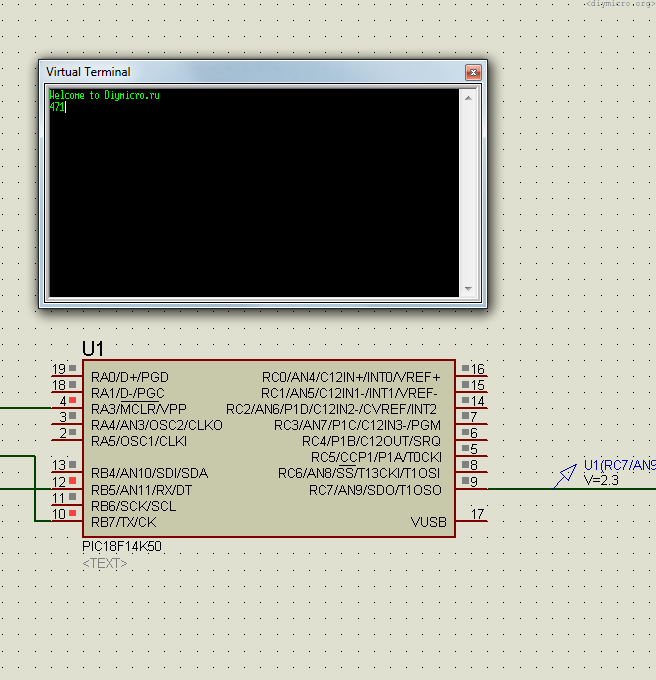
So, 471*5000/1024 = 2299.80 mV, not bad, first try and we right here. Lets try the interrupts now. The principle is absolutely same, just instead of waiting in the main cycle we working with interrupt routine:
void main()
{

 TRISC7 = 1;
 ANSEL = 0;                                                                   //here all analog buffers off
 ANSELH = 2;																  //turn on analog input for RC7(AN9)
 ADCON0 = 0b00100100;														  //Channel AN9 select
 ADCON2 = 0b10000100;														  //Right justification, clock = Fosc/4
 ADON = 1;																	  //ADC is enabled!!!
 TRISB7 = 0; //TX pin set as output
 TRISB5 = 1; //RX pin set as input

 Vmeas = 0;

 UARTConfig = USART_TX_INT_OFF & USART_RX_INT_OFF & USART_ASYNCH_MODE & USART_EIGHT_BIT & USART_BRGH_HIGH ;    //прерывания выключены, асинхронный режим, 8 бит, высокоскоростной режим
 baud = 77;                 //Focs/(9600*16) - 1
 OpenUSART(UARTConfig,baud);


 putsUSART( (char *) "Welcome to Diymicro.ru\r\n" );

 ADIF = 0;
 ADIE = 1;
 PEIE = 1;
 GIE = 1;


 GO = 1;																	   //go, go, go!!! (:


 while(1)
 {
 		if (ADCstatus)
 		{
 			Vmeas = (ADRESH << 8) | ADRESL;
 			NumToUart(Vmeas);
 			ADCstatus = 0;
 		}


 }

}


void interrupt isr()
{
	if (ADIF)
	{
		ADCstatus = 1;
		ADIF = 0;

	}
}
Worked exactly like previous, the same value has been generated.
This is fine, but now I want to try something more practical, let me try to apply a sinewave to the input. First of all what frequency we could digitize normally? I made some experimental calculations and determined that time between conversions is ~13 us, I want to have at least 128 values per period, so 128 * 13 = 1664 us, or somewhat about 601 Hz, we can just average it to 600Hz.
To save digitized values I created 128 bytes array, to which all data was saved:
#include <xc.h>
#include <plib/usart.h>
#include <plib/delays.h>


#define _XTAL_FREQ 12000000 //The speed of your internal(or)external oscillator

#pragma config WDTEN = OFF, LVP = OFF, FOSC = HS

unsigned char UARTConfig = 0;
unsigned char baud = 0;
unsigned int Vmeas[128] = 0;
volatile bit ADCstatus = 0;
volatile unsigned char i = 0;

void Delay1us();          //1us delay for 12MHz xtall
void DelayUs(unsigned char Us);
void DelayMs(unsigned int Ms);
void NumToUart(unsigned int Num);

/*
 *
 */
void main()
{

 TRISC7 = 1;
 ANSEL = 0;                                                                   //here all analog buffers off
 ANSELH = 2;																  //turn on analog input for RC7(AN9)
 ADCON0 = 0b00100100;														  //Channel AN9 select
 ADCON2 = 0b10000100;														  //Right justification, clock = Fosc/4
 ADON = 1;																	  //ADC is enabled!!!
 TRISB7 = 0; //TX pin set as output
 TRISB5 = 1; //RX pin set as input


 TRISC5 = 0;

// Vmeas = 0;


 UARTConfig = USART_TX_INT_OFF & USART_RX_INT_OFF & USART_ASYNCH_MODE & USART_EIGHT_BIT & USART_BRGH_HIGH ;    //прерывания выключены, асинхронный режим, 8 бит, высокоскоростной режим
 baud = 77;                 //Focs/(9600*16) - 1
 OpenUSART(UARTConfig,baud);


 putsUSART( (char *) "Welcome to Diymicro.ru\r\n" );

 ADIF = 0;
 ADIE = 1;
 PEIE = 1;
 GIE = 1;


 GO = 1;																	   //go, go, go!!! (:


 while(1)
 {
 		if ((ADCstatus)&&(i<128))
 		{
 			Vmeas[i] = (ADRESH << 8) | ADRESL;
 			//NumToUart(Vmeas);
 			//putsUSART( (char *) "\r\n" );
 			i++;
 			ADCstatus = 0;
 			GO = 1;
  		} else
  			{
  				if ((i == 128)&&(ADCstatus))
  				{
  					ADCstatus = 0;
  					for (i=0;i<128;i++)
  					{
  						 NumToUart(Vmeas[i]);
  						 putsUSART( (char *) "\r\n" );
  					}
  				}
  			}


 }

}


void interrupt isr()
{
	if (ADIF)
	{
		ADCstatus = 1;
		ADIF = 0;


	}
}


void Delay1us()         //delay approx 1 us
{
  Delay1TCY();
  Delay1TCY();
  Delay1TCY();
}

void DelayUs(unsigned char Us)      //delay for a given number of microseconds
{
  for (unsigned char i = 0; i<Us; i++)
    Delay1us();
}

void DelayMs(unsigned int Ms)      //approx delay for a given number of miliseconds
{
  for (unsigned int i=0; i<Ms; i++)
    Delay1KTCYx(3);
}

void NumToUart(unsigned int Num)                                                //Число в уарт
{

  unsigned int bignum = 10000;
  unsigned char numtemp = 5;

  if (!Num)
  {
      WriteUSART('0');         //Выталкиеваем все разряды - от старшего к младшему
      while(BusyUSART());                                                       //Ждем пока освободится модуль иначе будут прострелы
  }
  else
  {
	  while(numtemp>0)                                                             //Определяем сколько разрядов имеет наше число
	  {
	    if (Num/bignum)
	        break;
	    numtemp--;
	    bignum = bignum / 10;
	  }


	  for (unsigned char i = numtemp; i>0; i--)
	    {
	      WriteUSART( (Num - (Num/(bignum*10))*bignum*10 )/bignum + '0');         //Выталкиеваем все разряды - от старшего к младшему
	      while(BusyUSART());                                                       //Ждем пока освободится модуль иначе будут прострелы
	      bignum = bignum/10;
	    }
   }
}
As soon as counter counted 128 conversions, the array is thrown to the terminal, and I can use the data:
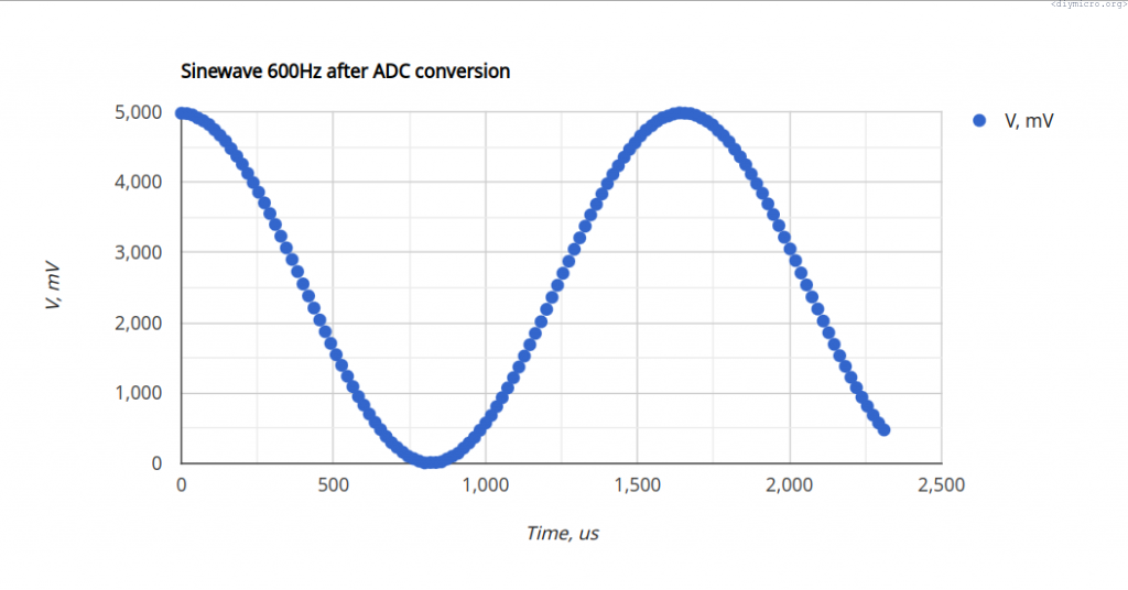
After plotting of the data I realized that my experimentally determined conversion time was not accurate and requires adjustment, having in mind that input frequency is 600Hz we need keep changing the unit time till we reach the matching, after this updated value is 18.2us.
Now, it would be not a bad idea to try this on a real chip. Unfortunately, I don’t have a sinewave generator, so I just swept the input voltage (and used this time 3.3V vdd):
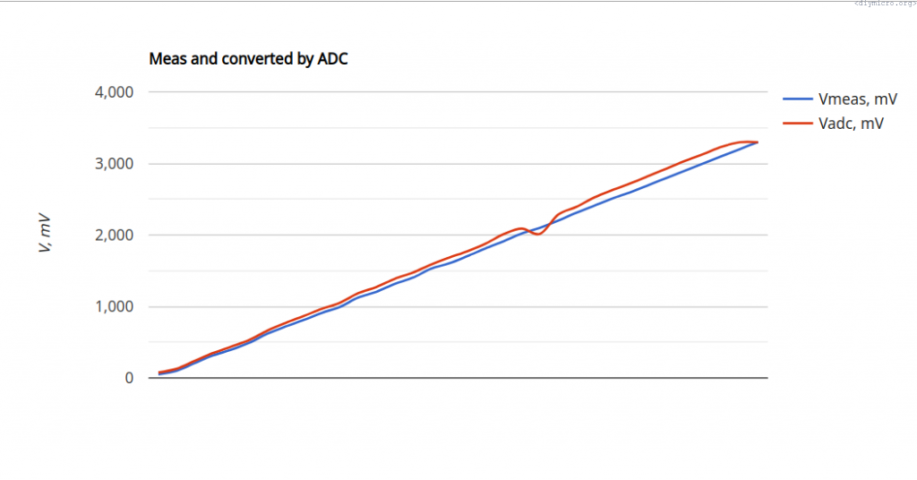
There is some mistake in the middle and saturation in the end, but beside this for it is good enough for my purposes.
As usual, the source source code