At some point of time we built together with my daughter a simple mechanical elevator and then I had an idea – why not to make it motorized and have just couple of buttons and have a bit of experience with the H bridges and motors.

At some point of time we built together with my daughter a simple mechanical elevator and then I had an idea – why not to make it motorized and have just couple of buttons and have a bit of experience with the H bridges and motors.
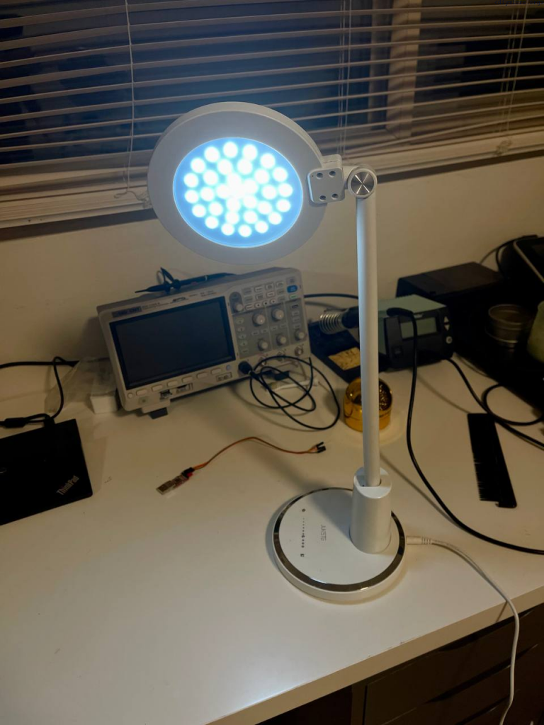
At some point I got the cheap lamp from amazon, it costs about 12$ but worked surprisingly well till some point… Looking under the hood revealed some ugly solutions:
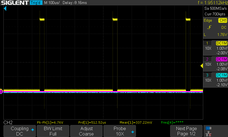
Task: To study the PWM module usage for LED brightness control
Tools: PIC18f1230, scope
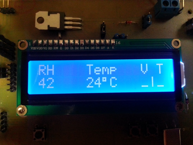
Task: To study the possibility of using of the DIY touch capacitive sensor on the pcb
Tools: PIC18f1230, a pcb with exposed square copper areas
So long story short, my cheap amazon lamp did not survive for a long time, but I really did like the LED light it gave. In the article below I will describe how to use a copper pad and the pic microcontroller without much additional circuitry.

Recently, I was constantly struggling with the fact that microchip was removing more and more support libraries, so it was not wise to rely on them in all projects. Anytime I return again to my old functions – if it used the support libs, there is a pretty good chance it is screwed.
So this code works with XC8 version 2.36 and doesn’t require the involvement of extra support lib.
Continue readingWhen I started to dig into USB topic it was quite a surprise, the amount of efforts the smart people around the world put into it just unbelievable. Even more fascinating fact – it actually worked out. The excitement reached some saturation when I realized the prices (: Vendor ID will cost you 5 grands per year, want to use a USB logo – no problem, just add another 6 grands on the top. Now we could test the compliance of your device with our standard for n grands… The companies using USB are listed on the website www.usb.org (USB Implementers Forum – USB-IF). The curious one could just count a number of companies and calculate the profit just from the year subscription, and this thing is going on for a long long time already. Well they have definitely built an addictive stuff. I, personally, have found the usage for my projects a bit excessive, I definitely not ready to put 5 grands per year for USB in the cheap humidity sensor.
Now, there are tons of different information, it is really challenging to grasp all at once, I will be honest and won’t pretend that I got everything, have a lot of holes in the knowledge, I just need to make it alive and respond to my commands. So, what I gonna to do is to show the info which looked important to me and then will conduct two experiments on this “foundation”.

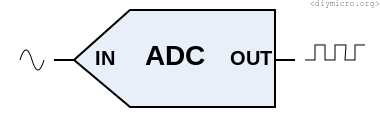
I was working on a small project where I needed to catch a certain button pressed event. Sounds simple initially, but I have 10 such buttons and it means that I need to have 10 IOs, or port expander, or make a digital matrix button handler (like 3×4 keypad) but these all variants are boring, I wanted something more interesting and make something like a DAC based on these buttons which will be digitazed by the built-in ADC in pic18f14k50. Thus, we will use a single port instead of 10, by cost of the more complicated code.
Let me start as usual – from reading of the datasheet.
Continue readingA situation in place was the next – my half done amplifier was working already 3 years just proving the statement “there last longing device is a temporary one”. It was kind of fine – but it consumes an energy. In a fact a solid chunk of the energy – it is class A amplifier. At some point in time I started to think – why to not switch on/off the amplifier in dependence on the signal presence.

The situation: there are two bathrooms, which have fans controlled manually.
The goal:
Let’s go.
Continue reading