The goal: to learn the CCP module
What do we have: PIC16f628a, the simple devboard + proteus.
I’m going to take a look into the CCP module (Capture/Compare/PWM).
Looking at the name you already can say that you can:
1. Capture
2. Compare
3. Generate PWM pulses
More stuff inside
We have the ССP1CON register:

CCP1X:CCP1Y – a bit later about these bits
CCP1M<3:0> – mode of operation:
0000 = all if OFF
0100 = capture, each falling edge
0101 = capture, each rising edge
0110 = capture, each 4th rising edge
0111 = capture, each 16th rising edge
1000 = compare, output to logic high when there is a match
1001 = compare, output to logic low when there is a match
1010 = compare, the interrupt will be generated
1011 = compare, a special event switching
11хх = PWM mode
First is the capture module:
The data from TMR1H and TMR1L registers are copied to CCPR1H and CCP1L having the next conditions:
- each falling edge of RB3
- each rising edge of RB3
- each 4 rising edge RB3
- each 16 rising edge RB3

There are two conditions to meet to use the module correctly:
- A pin RB3 should be the input
- TMR1 should be configured as a timer or a counter
Will not provide any code example about it, not that often is this feature going to be used.
Compare: In this mode register, CCP1 compared to the register TMR1. If there is a match the output RB3 can be changed or the interrupt will be generated.

The next conditions should be met:
- RB3 is the output
- The timer TMR1 is synchronized internally (Focs/4)
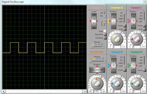
For this one I made a simple program to generate 1ms pulses
#include <htc.h>
#define _XTAL_FREQ 4000000

__CONFIG(WDTDIS & UNPROTECT & MCLREN & LVPDIS);

void main() {
unsigned char x;
__delay_ms(100);
TRISB = 0x00;
PORTB = 0x00;

CCPR1H = 0b00000011; CCPR1L = 0b11101000; // 1000 in CCPR1
CCP1M3 = 1;                               //
CCP1M2 = 0;
CCP1M1 = 1;
CCP1M0 = 0;

T1CKPS1 = 0;
T1CKPS0 = 0;  // Prescaler = 0

T1OSCEN = 0;
TMR1CS = 0;   // Fosc/4
TMR1ON = 1;
T1SYNC = 0;

GIE = 1;
PEIE = 1;
CCP1IE = 1;

for (;;) {

}

}

void interrupt isr() {
if (CCP1IF) {
RB3 = !RB3;
TMR1H = 0x00; TMR1L = 0x00;
CCP1IF = 0;
}

}
The source code
The most often used application is actually PWM, I think it deserves a separate experiment, so please go to experiment #11 to check it out.
Pingback: PIC мк. Эксперимент №10. Использование модуля CCP (Capture/Compare). | PIC микроконтроллеры