I choose the software realization of the I2C protocol as the next experiment. There isn’t a description of this protocol, only realization. The curious soul should google it, there is a lot information on i2c subject.
So:
Goal: To make the connection between PIC16f628a and IO port expander PCA9539 by i2c
What we have: PIC16f628a, PCA9539, devboard.
Why do I need it (in short): I have one project in development state for now. The project is a clock with a thermometer and two seven-segment indicators: the first 4-digit and the second has 3 digits. To control it I need 8+4+8+3 = 23 IO pins, but PIC16f628a has only 16, so in the such configuration, it seems not real to me. In the beginning, I thought about shift register using, but suddenly I received free sample sets from NXP and I took the decision to use PCA9539. In this case, there are only 9 pins to be used, and two pins from it are for I2C communication between pic micro, RTC clock, and the thermometer.
Let’s look inside of io expander:
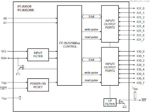
There are two pins used for address and one output used for the interrupt, except 16 IO pins. An address formed by pins A0 and A1, like that:

I just pull these pins to the ground, so in my case, it looks like:
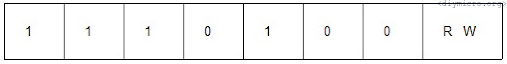
This byte we have to use for all command sequences to the IO expander.
The next byte is the command byte, which points to the place where we’re going to write information (configuration byte, IO ports, etc).
*Numbers below are written in decimal form.
| 0 | Input port 0 |
| 1 | Input port 1 |
| 2 | Output port 0 |
| 3 | Output port 1 |
| 4 | Por 0 polarity inversion |
| 5 | Port 1 polarity inversion |
| 6 | Port 1 configuration byte |
| 7 | Port 2 configuration byte |
You need to remember if you want to work with this IC, registers always work in pairs, so if you write the first register, you have to write the second, too. The command byte simply indicates the order of writing registers.
In general, write sequence looks like that:
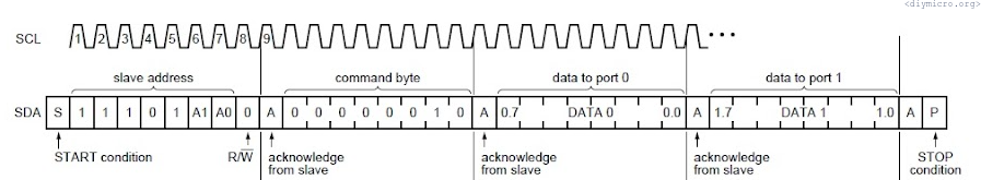
Let’s try to learn how to write by I2C. And right away move to code, the main feature here is that we work not with direct port values but with the direction of the port. Obviously, we should do the next thing:
#define SCL TRISB6
#define SDA TRISB5

#define SCL_IN RB6
#define SDA_IN RB5
And here is delay for clock:
void i2c_delay (void)

{

__delay_us(10);

}
Start procedure:
void i2c_start(void)  //

{

SCL = 1;
SDA = 1;

i2c_delay();
SDA = 0;
i2c_delay();
SCL = 0;

}
End of sequence procedure:
void i2c_stop (void)

{

SDA = 0;

i2c_delay();

SCL = 1;

i2c_delay();

SDA = 1;

i2c_delay();

}
Write procedure:
bit i2c_tx(unsigned char d)

{

char x;

static bit b;

             for (x=0; x<8; x++) {    //8 bits transmit
                             i2c_delay();
                             if (d&0x80) SDA = 1;
                             else SDA = 0;
                             i2c_delay();
                             SCL = 1;
                             d <<= 1;
                             i2c_delay();
                             SCL = 0;   }
i2c_delay();
i2c_delay();
SDA = 1;              //prepare to ACK
SCL = 1;
i2c_delay();
b = SDA_IN;    //recieve ACK bit
SCL = 0;
return b;           //Return ACK value
}
Now we have all that we need to write to the IO expander by I2C. Let’s show 2-digits number on the seven-segment display, which will increment by 1 for every button push.
Number to display function:
void dispo(unsigned char temp)

{
unsigned char i = 0;
i = temp/10;
maj= 0; min =0;
i2c_start();
i2c_tx(0b11101000);
i2c_tx(0b00000010);
i2c_tx(digit[i]);
i2c_tx(digit[i]);
i2c_stop();
maj= 1; min = 0;
__delay_ms(5);
i = temp - (temp/10)*10;
maj= 0; min = 0;
i2c_start();
i2c_tx(0b11101000);
i2c_tx(0b00000010);
i2c_tx(digit[i]);
i2c_tx(digit[i]);
i2c_stop();
maj= 0; min = 1;
__delay_ms(5);
}
The read procedure is going to be investigated in another experiment and for another device (I’m waiting for the package from China )
Pingback: Pic Lab, PIC16, Experiment #15, Real-time clock (RTC) DS1307 | diymicro.org