Auto enabling/disabling of the amplifier

A situation in place was the next – my half done amplifier was working already 3 years just proving the statement “there last longing device is a temporary one”. It was kind of fine – but it consumes an energy. In a fact a solid chunk of the energy – it is class A amplifier. At some point in time I started to think – why to not switch on/off the amplifier in dependence on the signal presence.

the pcb for auto turn on/off feature
Continue reading

Pic Lab, PIC16, Experiment #15, Real-time clock (RTC) DS1307

I got the package from China with some ICs I wanted to try before embedding them to the clock project I want to make. Have to warn: my point of interest was just a time, the date was out of the scope, so nothing about it will be investigated further.

Goal: To write the value of the time/read the time and output it thru UART from the DS1307 chip

Tools: PIC16f628a, DS1307, MAX232 level converter, devboard, proteus.

Continue reading

Pic Lab, PIC16, Experiment #14, USART (UART) module

Let’s look at USART module in pic microcontroller (uart module).

I’m going to move in two ways:

1. Using existing functions from a hi-tech compiler.

2. Writing my own functions.

USART = UART = SCI – the universal data transmitting/receiving protocol, which can work in synchronous and asynchronous modes. We pay attention to the second mode at the moment, this one is used for communications mostly.

Continue reading

Pic Lab, PIC16, Experiment #13, Software I2C

I choose the software realization of the I2C protocol as the next experiment. There isn’t a description of this protocol, only realization. The curious soul should google it, there is a lot information on i2c subject.

So:

Goal: To make the connection between PIC16f628a and IO port expander PCA9539 by i2c

What we have: PIC16f628a, PCA9539, devboard.

Why do I need it (in short): I have one project in development state for now. The project is a clock with a thermometer and two seven-segment indicators: the first 4-digit and the second has 3 digits. To control it I need 8+4+8+3 = 23 IO pins, but PIC16f628a has only 16, so in the such configuration, it seems not real to me. In the beginning, I thought about shift register using, but suddenly I received free sample sets from NXP and I took the decision to use PCA9539. In this case, there are only 9 pins to be used, and two pins from it are for I2C communication between pic micro, RTC clock, and the thermometer.

Continue reading

Pic Lab, PIC16, Experiment #12, EEPROM

Goal: To write and read EEPROM

What we have: PIC16f628a and a simple devboard.

Microcontroller PIC16f628a has 128 bytes of EEPROM memory on board, not too much but we have what we have. Hi-tech PICC compiler has internal functions for work with EEPROM, but here I’m going to make some my personal functions.

Let’s look at the EECON1 register:

ee
from the mikroe resourse
Continue reading

Pic Lab, PIC16, Experiment #5: interruptions

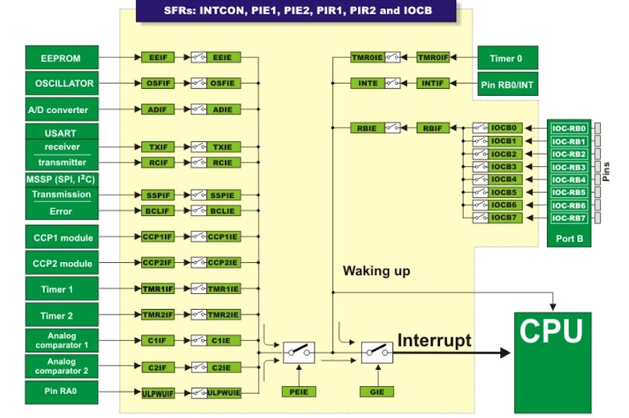
Interruptions are one of the great things about microcontrollers, if you want to do something fast, reliable, and simple… well, not exactly simple in a programming language sense perhaps, but really simpler from the hardware perspective point of view. So, the main purpose of interruption is to interrupt your main program cycle and do whatever you want in case of that event (a timer has reached the settled time, a button has been pressed, and so on). Here is the picture from the mikroe ebook (www.mikroe.com), just because they really made quite nice pictures and quite a nice manual by the way.

Going further…

Continue reading

Pic Lab, PIC16, Experiment #4: 7 segment display

It was 2012 year, I was just starting to learn how to work with the PIC microcontrollers, so the code is far away from optimal.

uC: PIC16F628a

Compiler: Hi-TECH PICC

Goal: To connect 7 segment indicator and display numbers from 0 to 9

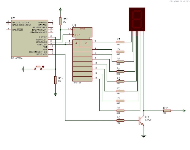
7 segment indicator connection
Continue reading