Goal: To measure the temperature using the DS18b20 temperature sensor
Tools: PIC16f628a, DS18b20, MAX232 level converter, devboard, proteus.
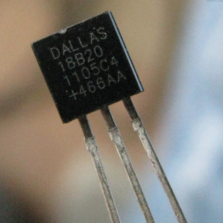
This article contains an example of working with a single DS18b20 sensor, by developing functions to work with the 1-wire protocol.
Our goal is to get the temperature with minimal effort, so the first thing is to carefully read the datasheet and learn about the chip we’re going to use. There is a couple of important moments in the datasheet, one of them is the supply voltage organization especially when you have tons of sensors on a single line. It was not my situation though, so I just use a regular way to route supply:
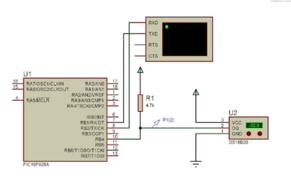
The data line should be tied to the vdd through a resistor (the datasheet recommends 4.7 KOhm). Reading the datasheet further – the memory organization:
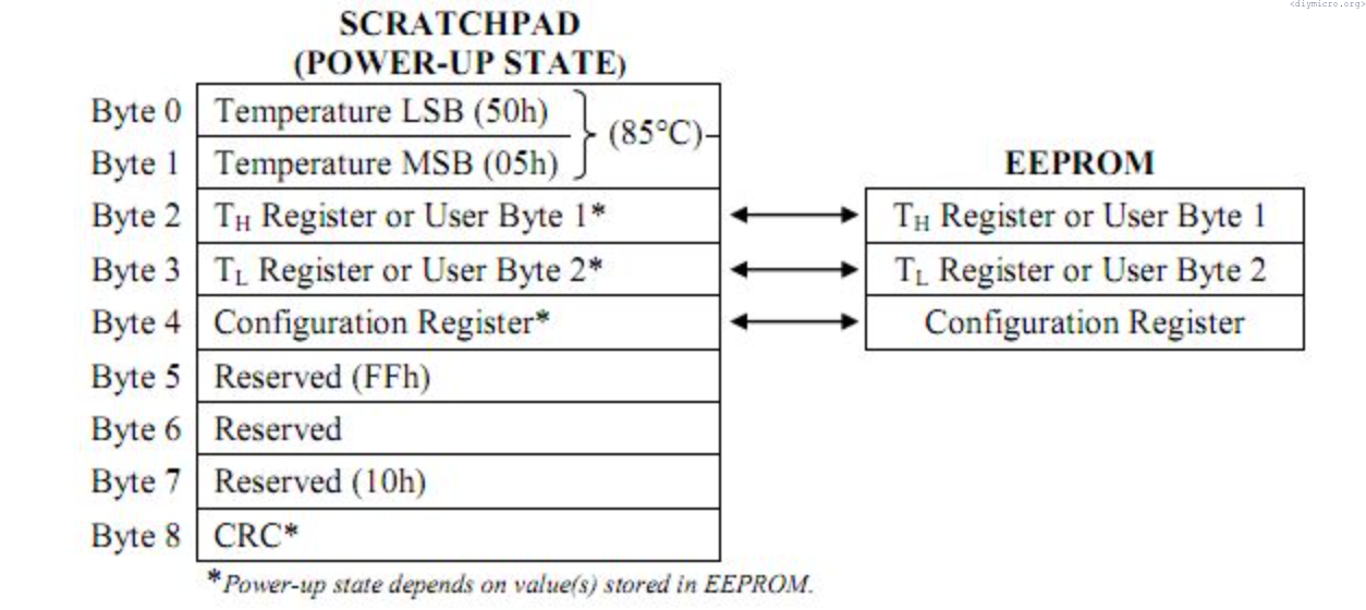
The 9 bytes only:
- Temperature LSB bit
- Temperature MSB bit
- high value trigger
- low value trigger
- the config register
- no idea what they used it for
- no idea what they used it for
- no idea what they used it for
- CRC
What normal person need – 0, 2 and 4.
The 4th one is the configuration register:

The register basically has just bits 5 and 6 for rewriting, not a lot of setups, huh. The default value for the sensor resolution is 12 bits, which corresponds to the 0.0625C degree accuracy, but there are some other possibilities:
- 9 bits – 0.5C
- 10 bits – 0.25C
- 11 bits – 0.125C
the short table with a summary is below:
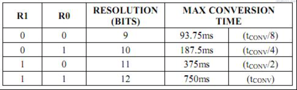
I would also recommend taking a look at the conversion time, you should allow this time after each conversion command, so better to let it settle fully to not get any extra bugs.
Now, let’s examine the temperature registers by themself:
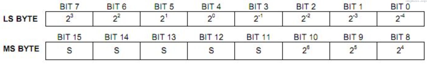
The lsb byte has 4 lsb bits for the fractional value of the temperature, while the decimal part is distributed across both bytes. S bits are the negative or positive sign indicator, 1 means that we are freezing.
Now is the time to look into the procedures which allow working with the one-wire interface, the first one is the initialization procedure:
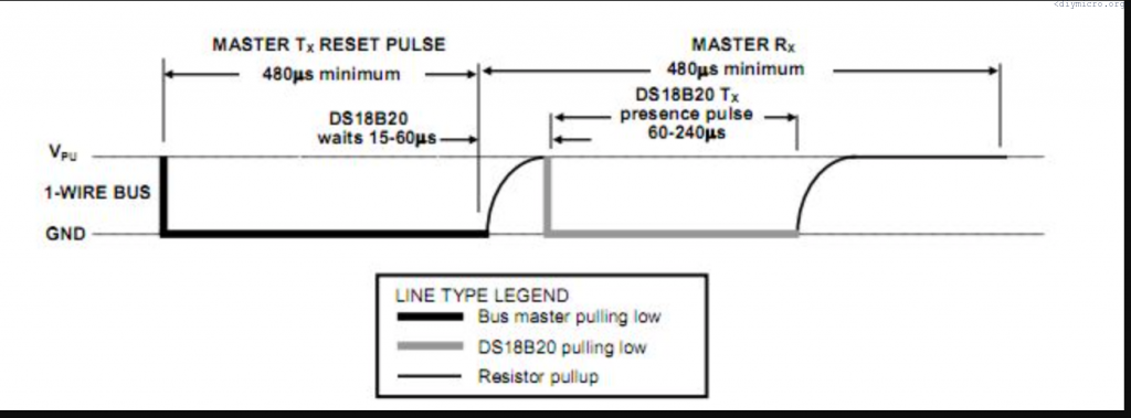
The microcontroller should firstly pull the line to the ground for at least 480 us, then put the HiZ state and check if the sensor will also pull the line to the ground. If there is ground level – all is OK, the sensor is here and we are ready to proceed further if not – we are shouting signals to the space. We need to create a function for this, don’t forget that we need to operate with the port state rather than with the values of its output.
First we need to define this:
#define STATE TRISB4
#define PIN RB4
And then the function by itself:
static bit INIT(void){
static bit b;
STATE = 1;
STATE = 0;         //line to ground
__delay_us(500);   //wait 500us
STATE = 1;         //release the line
__delay_us(65);    //wait for 65us
b = PIN;           //check the line
__delay_us(450);   //wait again
return b;          //return the line value
}
The function returns 0 value if there is a sensor on the line and 1 if there is no sensor. The next function is the writing procedure:
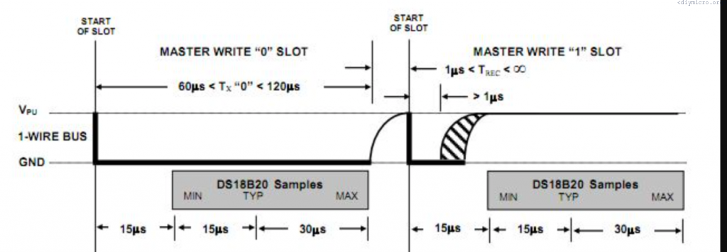
To write 0 to the sensor, the line should be pulled to the ground for 60us min, to write 1 – pull it to the ground for just 1 us, then release and wait the time according to the picture from the datasheet. Remember, LSB goes first:
void TX(unsigned char cmd){

unsigned char temp = 0;
unsigned char i = 0;
temp = cmd;
for (i=0;i<8;i++) {
                  if (temp&0x01) {
                                 STATE = 0;              //transfer 1
                                 __delay_us(5);
                                 STATE = 1;
                                 __delay_us(70);
                                 } else {                //transfer 0
                                        STATE = 0;
                                        __delay_us(70);
                                        STATE = 1;
                                        __delay_us(5);
                                        }
                                 temp >>= 1;
                 }
}
Now, the reading procedure:
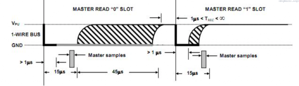
For the reading we should pull the line to the ground for 1us and then we have 15us to determine whether we have 0 or 1, the function is here:
unsigned char RX() {

unsigned char d = 0;
unsigned char i = 0;
for (i=0;i<8;i++){
                 STATE = 0;                 //line to the ground
                 __delay_us(6);
                 STATE = 1;

                 d>>=1;                     //dont remember already why I did this
                 if (PIN == 1) d |= 0x80;   //if line has high level, we read 1
                 __delay_us(70);            //wait as long as we should
                 }
return d;
}
Those 3 functions are all we need to work with the 1-wire interface. The routine of temperature reading follows (for the single sensor) :
- init
- 0xCC – skip the identification
- 0х44 – start the conversion procedure
- wait required time(750 ms for the 12 bits resolution)
- re-init
- 0xCC – skip the identification
- 0хBE – read the registers
I have created a separate procedure for this routine with a specific number conversions included:
void get_temp() {
static bit init;

unsigned char temp1;
unsigned char temp2;
init = INIT();
             if (!init) {                 //init is good?
                        TX(0xCC);
                        TX(0x44);
                        __delay_ms(150);  //wait 750 ms
                        __delay_ms(150);
                        __delay_ms(150);
                        __delay_ms(150);
                        __delay_ms(150); }
              init = INIT();              //reinit
              if (!init) {
                         TX(0xCC);
                         TX(0xBE);        //read
                         temp1 = RX();    //read lsb
                         temp2 = RX();    //read msb
                          }

temp_drob = temp1 & 0b00001111;           //fractional part to separate variable
temp_drob = ((temp_drob*6)+2)/10;         //conversion
temp1 >>= 4;
sign = temp2 & 0x80;                      //determine the sign
temp2 <<= 4;
temp2 &= 0b01110000;
temp2 |= temp1;                           //everything to the single variable

if (sign) {                               //if minus
            temperature = 127-temp2;      //
            temp_drob = 10 - temp_drob;   //
           }   else temperature = temp2;
}
to check if it works, I crated a simple circuit on a breadboard and used the uart:
void main() {
unsigned char input = 0;

init_comms();
get_temp();
printf("\ftemperatura -- ");
if (sign) printf("-"); else printf("+");
printf("%d", temperature);
printf(".%d", temp_drob);

while(1){
        input = getch();
        if (input == 50) {
                         get_temp();
                         printf("\r\ntemperatura -- ");
                         if (sign) printf("-"); else printf("+");
                         printf("%d", temperature);
                         printf(".%d", temp_drob);
                         }
       }
}
The result:
Warning: there was a discovery of the mistake related to the negative temperatures, I fixied the source code on the bitbucket. I warned you, so be prepared.