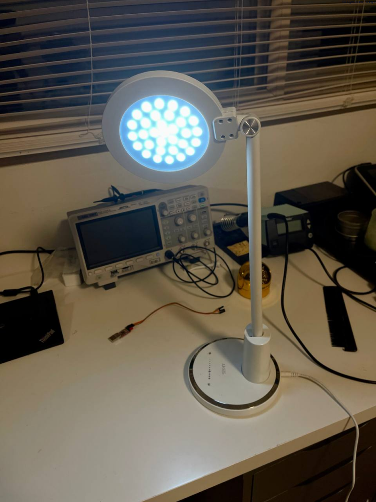
At some point I got the cheap lamp from amazon, it costs about 12$ but worked surprisingly well till some point… Looking under the hood revealed some ugly solutions:
- A horrible pcb routing
- An absence of filtering caps of supplies
- Really poor quality wiring
Initially, I had an idea to make adjustments here and there on the existing pcb, but the more I looked into the patient – more desperate to change everything I was. Sooo, at the some point the idea to change everything completely overwhelmed me and I went this way.
What do we need:
- Touch sensor based controls
- 2 PWM channels to drive 2 colors LED
- Watchdog to reset the device when it is going to frozen state
- Memory settings to remember which mode I turned the device off
Sounds pretty simple, but this appeared to be not as easy as I thought, especially in the touch sensors area – I need 9 control inputs to match completely with the existing lamp enclosure I have. And not just due to the difficult realization of the task – this is 2022 year, a chip shortage outdoors, and pic microcontrollers with 10+ channels ADC are not that easy to find (and definitely not for a cheap price). One of the cheapest pic microcontrollers with ADC at the time available on digi-key (I did not want any more experiments with Chinese counterfeits) was PIC18F1230, this guy has a pretty nice set of functions but only 4 ADC channels, so the usual methods of using touch sensors are kind of questionable.
First thing first – I need to make a decent PCB with next considerations:
- A decent supply routing with a regulator which can dissipate a large amount of the power (I’ve picked dpack package and usual 7805, although, technically it would be better to use here some dc-dc downconverter with a better efficiency) — as appeared later, there are already plenty of decent linear regulator with negligible bias current and ability to work with high input voltages.
- ICSP header
- UART connection ready (for the debug)
- repeat exact configuration of touch sensors copper as the original PCB to have the full compatibility with the lamp enclosure
- Scope probe points ready and, ideally, their impact should be minimized, since it likely we will have to make a sensitive to noise or extra cap sensor post-processing — again, as appeared later it is not that great idea. The passive probes impacting sensor significantly, I would suggest to use either active probes (if you reach enough) either make some kind of the shop probe (look into the black magic book 🙂 )
- Provide routing for the quartz as well, there is a huge possibility of using HS mode (for the more accurate and more frequent gathering of ADC results — with this uC not really needed, the ADC so crappy that it can’t handle higher speeds, so internal osc is pretty much okay
- PWM channels routed and nmos transistors used as buffers for LED output
PCB Schematic/layout
Okay, looks like the list is complete and we can make the schematic:

PIC18F1220 is used here since Eagle software did not have a PIC18F1230 at the moment for some reason. It was simply easier for me to reuse another SOIC 16 package than create a new element in my libraries.
After this a PCB has been designed:
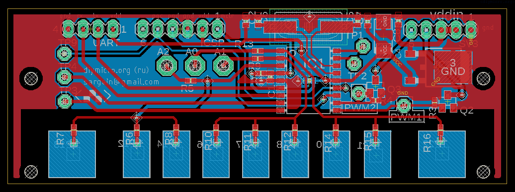
The next thing was new for me, I used to make my simple PCB by myself at home, using different methodologies. This time I decided to try finally order it from the PCB manufacturer, now it looks simpler and the price is somewhere nearby of home production 🙂
I used the Chinese company called PCBway, at 18th May order has been placed and they gave me such pictures of processed gerber files:


Will see how good/bad it will look when it will come, an exciting waiting time came now.
While waiting here is a plan draft for next steps:
- Assembly PCB
- Bring up UART on the board, so the debug procedure is going to be easier
- Work on a common method suggested by Microchip for the touch sensors
- Work on a more precise touch sensor control post-processing, trying to distinguish one of three sensors connected to the same ADC pin (going to be tought part I think)
- Work on bringing up PWM for both brightness and the color mode
- Add the watchdog so glitchy events will lead to a complete reset
- Embed a new PCB into the old enclosure and compose everything back as it was
- Enjoy the improved light
Okay, two weeks have passed and pcbs are in my mailbox:
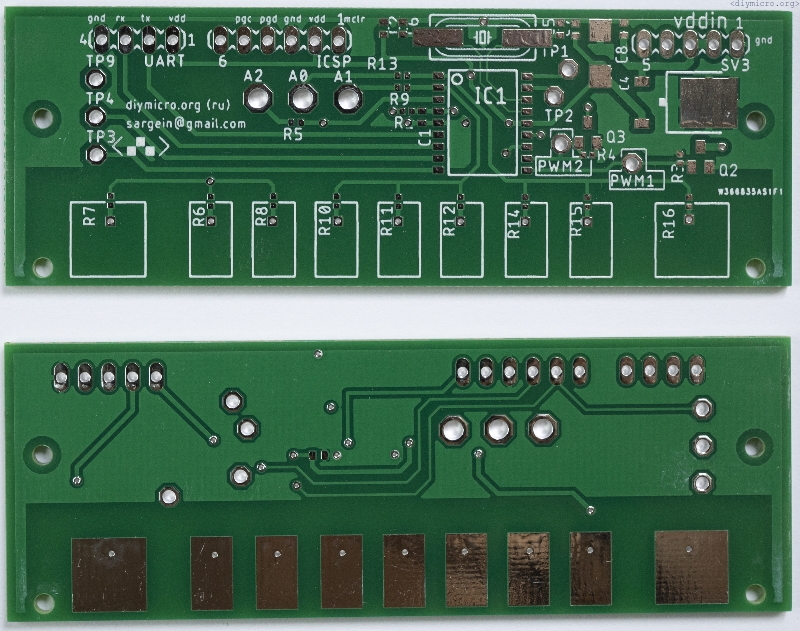
In principle, I’m happy with the build quality, except for this silver covering of pads. I found that it makes soldering process somewhat harder than usual copper.
UART interface
After components have been soldered it is time for #1: bring uart to work.
First of all, I tried to use my old method where I used just ready-to-go libraries from the xc8 compiler. As it appeared, after some version (perhaps later than 1.3), they removed completely those libs in the favour of using MCC and easy programming approaches. I tried to learn a bit this MCC tool but pretty quickly found that PIC18F1230 is not supported by the tool. This was a pathetic situation, but I survived 🙂 I needed just tx part, so quickly wrote couple functions for transmitting of the data.
A couple of days update, I needed RX part and workaround for interrupts, so my uart.c file now looks like this:
#include <xc.h>

void InitUart()  //Initialization of UART
{
    SPEN = 1;
    TRISA3 = 1;
    TRISA2 = 1;

    SYNC = 0;
    BRG16 = 0;
    BRGH = 0;
    SPBRG = 12; //9615 baudrate with 8MHz
    TX9 = 0; //no need to use 9th bit
    TXEN = 1;

    //Reciever part
    RCIE = 1;
    RX9 = 0;
    CREN = 1;

}//InitUart

char BusyUSART(void)
{
  if(!TXSTAbits.TRMT)  // Is the transmit shift register empty
    return 1;          // No, return FALSE
  return 0;            // Return TRUE
}


void writeByteUart(char tx_data)  //Writing of a single byte
{
  TXREG = tx_data;      // Write the data byte to the USART
}//writeByteUart

void writeDataUart( char *data)
{
  do
  {  // Transmit a byte
    while(BusyUSART());
    writeByteUart(*data);
  } while( *data++ );
}

void NumToUart(unsigned int Num)                                                //Число в уарт
{

  unsigned int bignum = 10000;
  unsigned char numtemp = 5;

  if (!Num)
  {
      writeByteUart('0');         //Выталкиеваем все разряды - от старшего к младшему
      while(BusyUSART());                                                       //Ждем пока освободится модуль иначе будут прострелы
  }
  else
  {
	  while(numtemp>0)                                                             //Определяем сколько разрядов имеет наше число
	  {
	    if (Num/bignum)
	        break;
	    numtemp--;
	    bignum = bignum / 10;
	  }


	  for (unsigned char i = numtemp; i>0; i--)
	    {
	      writeByteUart( (Num - (Num/(bignum*10))*bignum*10 )/bignum + '0');         //Выталкиеваем все разряды - от старшего к младшему
	      while(BusyUSART());                                                       //Ждем пока освободится модуль иначе будут прострелы
	      bignum = bignum/10;
	    }
   }
}


char ReadUart()
{
    char data;   // Holds received data
    data = RCREG;                      // Read data

  return (data);                     // Return the received data

}
I have not made it flexible, it is just fixed now for Fosc = 8MHz for common used baudrate 9620. writeByteUart() sends a single byte, and writeDataUart sends a string. Also, there is the old function I made for pushing the number thru uart.
For interrupts handling in PIC18 we shall use different levels of priority:
void low_priority interrupt LowIsr(void)
{

}

void high_priority interrupt HighIsr(void)
{

    if (TMR0IF)
    {
         tmr0flag = 1;
         TMR0IF = 0;
    }

    if (RCIF)
    {
       rx_data_recieved = ReadUart();
    }

}
An important note 1: flags should be cleared within the interrupt handling procedure, otherwise the program will stack inside of isr forever.
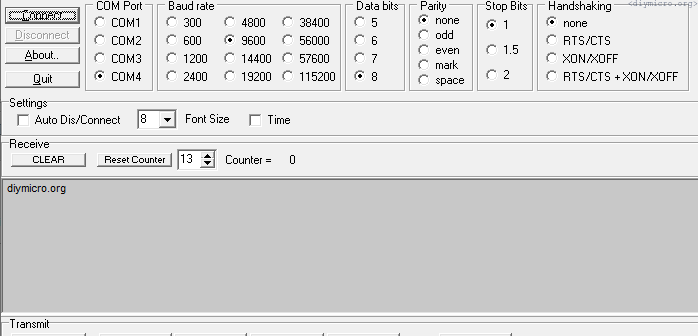
An important note 2: my beloved terminal software doesnt work good at win10, I have got so many error messages and spent time. When I switched to PuTTy software – no issues and all working fine.
An important note #3: I finally gave up and made own library and put together an additional experiment about uart in PIC18, it looks like it is a good time for this
Touch sensors
So now after the UART is functioning, it it time to look into how the touch sensor should operate. To help with that I have arranged a different experiment.
Now with all this info in mind I have a couple things to say:
- It is not quite reliable to use 9 pads with this pic microcontroller, rather I should use just 3
- I need to have a direct contact of the human finger with an exposed pad, not cool but we have what we have
- Memory saving – meh, I don’t think I need it. Lets keep things simple, I pretty sure I all the time will use similar setup – the coldest temperature of the light and the mid brightness.
So first thing first – need to provide somehow an electrical contact with 3 pads from the enclosure. Apparently they had a better way, I mean they had a more sensitive pads + post processing, so the plastic enclosure was not a barrier for them, but in my experiments I saw that I can’t easily ignore it – the sensitivity becomes quite horrible. What I ended up with is a just exposed pad by electrical contacts (I put a couple of screws through the plastic 🙂 )
So how do we setup the touch sensor finally? Well first of all we need to determine how sensors look untouched and save the values in memory.
volatile __bit timer0_event = 0;
volatile __bit reference_calibration = 0;
unsigned char timer_counter = 0;
unsigned char samples_count = 0;

void main()
{
//INTOSC TO 8MHz
 IRCF2 = 1;
 IRCF1 = 1;
 IRCF0 = 1;
 SCS1 = 1;
//INTOSC setup

 InitUart();
 writeDataUart((char *) "\r\ndiymicro.org\r\n");
 InitADC();
 ADIE = 0;

//launching the timer for reference calibration (~1ms)
 T0CS = 0;
 //T016BIT = 0; //16 bits counter
 T016BIT = 1; //8 bits counter
 PSA = 0;       //prescaler is used
 T0PS2 = 0;
 T0PS1 = 1;
 T0PS0 = 0;
 TMR0ON = 1;
 TMR0IF = 0;
 TMR0IE = 1;
//end of timer configuration


 IPEN = 0;
 RCIE = 0; //dont need uart rx interrupts
 GIE = 1;
 PEIE = 1;
 reference_calibration = 1;

// samples_count = 0;
// adcAN0digitalOne();
 while(1)
 {
    if ((timer0_event)&&(reference_calibration))
    {

        if (timer_counter == 0)
        {
        adcSelChan(0);
        adcAN0digitalOne();
        adcAN0analogIn();
        timer_counter = 1;
        } //if counter 0
            else
            {
                if (timer_counter == 1)
                {
                    adcSelChan(1);
                    adcAN1digitalOne();
                    adcAN1analogIn();
                    timer_counter = 2;
                }    //if counter 1
                    else
                    {
                        if (timer_counter == 2)
                        {
                            adcSelChan(2);
                            adcAN2digitalOne();
                            adcAN2analogIn();
                            timer_counter = 0;
                        }    //if counter 1
                    }//else 2
            }//else 1


        ADIE = 1;

        timer0_event = 0;
        GO = 1;
        TMR0IE = 1;
        TMR0ON = 1;
    }//if timer0

    //adc conversion ended, analizing outputs and restarting timer
 }//while(1)

}//main()


void __interrupt(high_priority) HighISR(void)
{


    if (TMR0IF)
    {
        //adcAN0digitalOne();
        //adcAN0analogIn();
        timer0_event = 1;
        TMR0IF = 0;
        TMR0IE = 0;
        TMR0ON = 0;
    }

    if (ADIF)
    {
          if (samples_count>=15)
          {
              samples_count=0;

          }else
          {
              samples_count++;
              GO = 1;
          }


        ADIF = 0;
    }//adif
}//high priority interrupts
This code produces pulses on all three inputs:
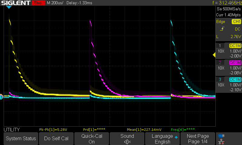
Looks nice and graphic and cool, but I found that the code has some flaws and the probes are impacting the measurements (need not to be a cheap and buy an active probe).
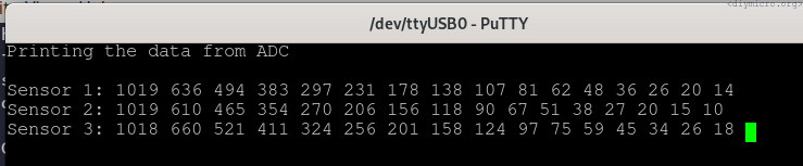
The code has been changed to this view, in order to produce values and throw them to the terminal:
void main()
{
//INTOSC TO 8MHz
 IRCF2 = 1;
 IRCF1 = 1;
 IRCF0 = 1;
 SCS1 = 1;
//INTOSC setup

 InitUart();
 writeDataUart((char *) "\r\ndiymicro.org\r\n");
 InitADC();
 ADIE = 0;

//launching the timer for reference calibration (~1ms)
 T0CS = 0;
 //T016BIT = 0; //16 bits counter
 T016BIT = 1; //8 bits counter
 PSA = 0;       //prescaler is used
 T0PS2 = 0;
 T0PS1 = 1;
 T0PS0 = 0;
 TMR0ON = 1;
 TMR0IF = 0;
 TMR0IE = 1;
//end of timer configuration


 IPEN = 0;
 RCIE = 0; //dont need uart rx interrupts
 GIE = 1;
 PEIE = 1;
 reference_calibration = 1;

// samples_count = 0;
// adcAN0digitalOne();
 while(1)
 {
    if ((timer0_event)&&(reference_calibration))
    {

        ADIE = 0;
        if (timer_counter == 0)
        {
            adcCH0Pol();
            timer_counter = 1;
        } //if counter 0
            else
            {
                if (timer_counter == 1)
                {
                    adcCH1Pol();
                    timer_counter = 2;
                }    //if counter 1
                    else
                    {
                        if (timer_counter == 2)
                        {
                            adcCH2Pol();
                            timer_counter = 3;
                        }    //if counter 1
                    }//else 2
            }//else 1


            if(timer_counter==4)            //when all 3 are finished
              {
                writeDataUart((char *) "\033c");
                writeDataUart((char *) "Printing the data from ADC\r\n");

              writeDataUart((char *) "\r\nSensor 1: ");
              for(i=0;i<16;i++)
              {
                adc_data_temp = temp0[i];
                adc_data_temp = (adc_data_temp<<8) | temp1[i];
                NumToUart(adc_data_temp);
                writeDataUart((char *) " ");
              }
              writeDataUart((char *) "\r\nSensor 2: ");
             for(i=0;i<16;i++)
              {
                adc_data_temp = temp2[i];
                adc_data_temp = (adc_data_temp<<8) | temp3[i];
                NumToUart(adc_data_temp);
                writeDataUart((char *) " ");
              }
              writeDataUart((char *) "\r\nSensor 3: ");
              for(i=0;i<16;i++)
              {
                adc_data_temp = temp4[i];
                adc_data_temp = (adc_data_temp<<8) | temp5[i];
                NumToUart(adc_data_temp);
                writeDataUart((char *) " ");
              }
              timer_counter = 0;
              __delay_ms(200);__delay_ms(200);__delay_ms(200);__delay_ms(200);__delay_ms(200);
              __delay_ms(200);__delay_ms(200);__delay_ms(200);__delay_ms(200);__delay_ms(200);
              __delay_ms(200);__delay_ms(200);__delay_ms(200);__delay_ms(200);__delay_ms(200);
              __delay_ms(200);__delay_ms(200);__delay_ms(200);__delay_ms(200);__delay_ms(200);

          }

        ADIE = 1;

        timer0_event = 0;
        GO = 1;
        TMR0IE = 1;
        TMR0ON = 1;
    }//if timer0

    //adc conversion ended, analizing outputs and restarting timer


 }//while(1)

}//main()


void __interrupt(high_priority) HighISR(void)
{


    if (TMR0IF)
    {
        timer0_event = 1;
        TMR0IF = 0;
        TMR0IE = 0;
        TMR0ON = 0;
    }

    if (ADIF)
    {

        if(timer_counter==1)
        {
            temp0[samples_count] = ADRESH;
            temp1[samples_count] = ADRESL;
        }
            else
            {
                if (timer_counter == 2)
                {
                    temp2[samples_count] = ADRESH;
                    temp3[samples_count] = ADRESL;
                }
                else
                {
                   if (timer_counter == 3)
                   {
                    temp4[samples_count] = ADRESH;
                    temp5[samples_count] = ADRESL;
                   }
                }
            }

          if (samples_count>=15)
          {
              samples_count=0;
              if (timer_counter == 3)
                    timer_counter = 4;

          }else
          {
              samples_count++;
              GO = 1;
          }


        ADIF = 0;
    }//adif
}//high priority interrupts
this code produces something like that at terminal:
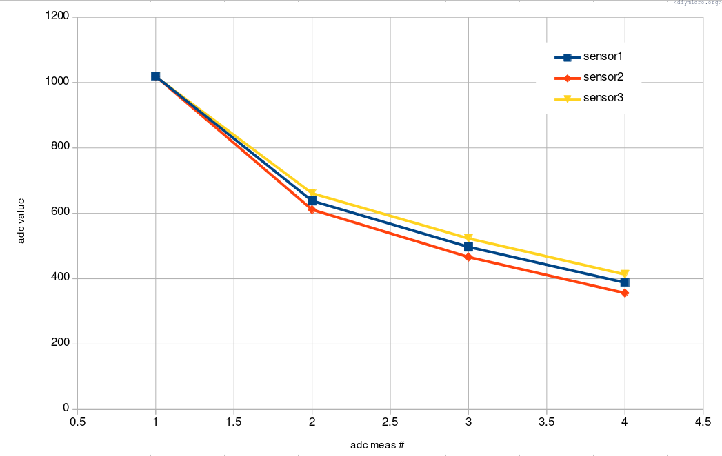
Now need to gather enough of the data to average and save them and get the reference curves we can use:
Next step is to choose a proper procedure to post-process the data of a single sensor:
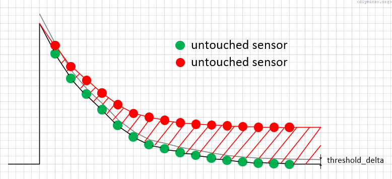
My idea is to compare each single point of the adc data with a reference data, and if it is larger than the threshold_delta then add +1 to the counter indicating that the sensor is touched. If we have more then 10 points indicating that sensor is touched – we say it is touched and return value 1.
To help me with that I firstly made a function which simply composes two char arrays to a single int one, for convenience:
void ADCtoGlobal(char adc_msb[16], char adc_lsb[16])
{
    char i = 0;

    for(i=0;i<16;i++)
    {
        adc_global_data[i]= adc_msb[i];
        adc_global_data[i] = (adc_global_data[i]<<8) | adc_lsb[i];
    }
}
And the the function to check if sensor is pressed by comparing the adc data with reference data + threshold value:
__bit IsSensorTouched(int ref_data[16],int adc_data[16], char threshold_delta)
{
    char i = 0;
    char positive_count = 0;

    for (i=0;i<16;i++)
    {
        if (adc_data[i]>(ref_data[i]+threshold_delta))
            positive_count++;
    }//

    if (positive_count>=10)
        return 0x01;
    else
        return 0x00;
}
Now we have some extra handy tools in our pockets. What we should do next, is to repeat the procedure couple times to average false things out. The question would be how long intervals we want between the next polling event and how many we events are good to average? I would like to have 2/3 of events to process, so the number 6 looks quite reasonable to me. Then if we would use like 40ms between polling then we will use about 250ms totally, and since it will be used for a power up we could make the refresh period really long (4s), that how it looks like on the scope:
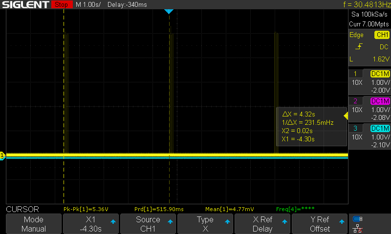

I chosen the pause between polling to be about 33ms, since it kind of convenient to make in power 2 system (it is pretty close to 32ms)
Now we have the tools to post-process the single sensor press, which is going to be a wake-up procedure:
//Waking up - working with a single sensor AN0
if (single_sensor)
{
//Forming 6 pulses
if ((pulses_counter==0)&&(timer0_event)&&(!adc_conversion_end))//first pulse is about to go
{
pulses_counter = 1;
timer0_event = 0;
timer0_33ms();
adcCH0Pol();
ADIE = 1;
GO = 1;
} //if pulses counter = 0
else
{
if ((pulses_counter>0)&&(timer0_event)&&(!adc_conversion_end))
{
if (pulses_counter>5) //time to wait a longer time
{
pulses_counter = 0; //reset a pulse counter
timer0_event = 0; //reset a timer0 flag just in case
timer0_4s(); //wait about 4 seconds
//writeDataUart((char *) "debug: we are in the 6th pulse area\r\n");
} else
{
pulses_counter++;
timer0_event = 0; //rest a timer0 flag
timer0_33ms();
adcCH0Pol();
ADIE = 1;
GO = 1;
}//else
} //if for next pulses
}//else
//End of Forming 6 pulses
//Processing of the data from ADC
if ((adc_conversion_end)&&(!timer0_event))
{
ADCtoGlobal(temp0,temp1);
if (IsSensorTouched(sensor1_ref,adc_global_data,threshold_delta_lamp))
{
sensor1_touch_counts++;
}
adc_conversion_end = 0;
if (pulses_counter==6) //last pulse in a pack
{
if (sensor1_touch_counts>2)
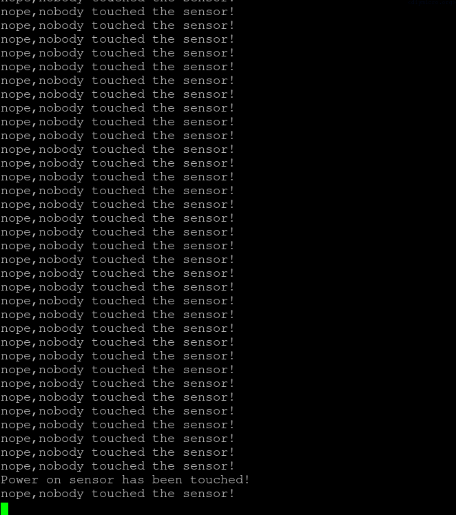
writeDataUart((char *) "Power on sensor has been touched!\r\n");
else
writeDataUart((char *) "nope,nobody touched the sensor!\r\n");
sensor1_touch_counts = 0;
}
} //if (adc_conversion_end)
}//if single sensor
//END of waking up procedure and a single sensor AN0And the interrupts for it looks like this:
void __interrupt(high_priority) HighISR(void)
{


    if (TMR0IF)
    {
        timer0_event = 1;
        TMR0IF = 0;
        TMR0IE = 0;
        TMR0ON = 0;
    }

    if (ADIF)
    {


        if (single_sensor)          //running adc for a single sensor
        {
            temp0[samples_count] = ADRESH;
            temp1[samples_count] = ADRESL;


          if (samples_count>=15)
          {
            ADIE = 0;
            adc_conversion_end = 1;
            samples_count = 0;

          }else
          {
              samples_count++;
              GO = 1;
          }


        ADIF = 0;
        }//if
    }//adif
}//high priority interrupts
This code works pretty solid:
The next step is to move from the state with a single sensor to 3 sensor and create a procedure for their post processing.
For this one I use a next logic:
- Launch sensor1 – timer 4ms
- Launch sensor2 – timer 4ms
- Launch sensor3 – timer 4ms
- clear all variables to reset to sensor1, – timer 500ms
- Repeat the polling N times (define experimentally)
Separately, keep processing adc data and determine which one has been pressed.
On a scope again it looks like this:


And the code for 3 sensors:
if (!single_sensor)
    {
      if (!adc_conversion_end)
      {
        if (pulses_counter==0)//check if we dont have the timer launched yet
        {
            timer0_250ms();
            pulses_counter = 1;
            sensor_in_work = 0;
            //writeDataUart((char *) "debug: first stage - time 1 s\r\n");
        }
            else
            {
                 if (timer0_event)//first pulse is about to go
                {

                     timer0_event = 0;
                     //writeDataUart((char *) "debug: second stage - entering to the polling\r\n");

                    switch (sensor_in_work)
                    {
                        case 0 :
                        {
                           // writeDataUart((char *) "debug: sensor 0 stage\r\n");
                            sensor_in_work = 1;
                            timer0_4ms();
                            adcCH0Pol();
                            ADIE = 1;
                            GO = 1;
                            break;
                        }
                        case 1 :
                        {
                           // writeDataUart((char *) "debug: sensor 1 stage\r\n");
                            sensor_in_work = 2;
                            timer0_4ms();
                            adcCH1Pol();
                            ADIE = 1;
                            GO = 1;
                            break;
                        }
                        case 2 :
                        {
                            //writeDataUart((char *) "debug: sensor 2 stage\r\n");
                            sensor_in_work = 3;
                            timer0_4ms();
                            adcCH2Pol();
                            ADIE = 1;
                            GO = 1;
                            break;
                        }
                        case 3 :
                        {
                                                sensor_in_work = 0;
                                                //writeDataUart((char *) "debug: end of the sensor sweep\r\n");
                                                if (pulses_counter<9)
                                                    {
                                                        pulses_counter++;
                                                        ADIE = 0;
                                                        timer0_33ms();
                                                    }
                                                else
                                                {
                                                    pulses_counter = 0;
                                                    timer0_250ms();    //another round is coming
                                                }
                        }


                    }//switch


                } //else

            }//else
        } //adc conversion ended


        //Processing of the data from ADC
        if ((adc_conversion_end)&&(!timer0_event))
        {
                 ADCtoGlobal(temp0,temp1);
                 if (IsSensorTouched(sensor1_ref,adc_global_data,threshold_delta_lamp))
                    sensor1_touch_counts++;

                 ADCtoGlobal(temp2,temp3);
                 if (IsSensorTouched(sensor2_ref,adc_global_data,threshold_delta_lamp))
                    sensor2_touch_counts++;

                 ADCtoGlobal(temp4,temp5);
                 if (IsSensorTouched(sensor3_ref,adc_global_data,threshold_delta_lamp))
                    sensor3_touch_counts++;


                 adc_conversion_end = 0;
                 if (pulses_counter==9)         //last pulse in a pack
                 {

                    if (((sensor1_touch_counts)>(sensor2_touch_counts))&&((sensor1_touch_counts)>(sensor3_touch_counts)))
                    {
                        if (sensor1_touch_counts>4)
                            writeDataUart((char *) "sensor 1 has been touched!\r\n");
                    }

                    if (((sensor2_touch_counts)>(sensor1_touch_counts))&&((sensor2_touch_counts)>(sensor3_touch_counts)))
                    {
                        if (sensor2_touch_counts>4)
                            writeDataUart((char *) "sensor 2 has been touched!\r\n");
                    }

                    if (((sensor3_touch_counts)>(sensor1_touch_counts))&&((sensor3_touch_counts)>(sensor2_touch_counts)))
                    {
                        if (sensor3_touch_counts>4)
                            writeDataUart((char *) "sensor 3 has been touched!\r\n");
                    }

                    sensor1_touch_counts = 0;
                    sensor2_touch_counts = 0;
                    sensor3_touch_counts = 0;

                 }

        }   //if (adc_conversion_end)


    }//if (!single_sensor)
And the interrupts:
else
            {
                if (sensor_in_work == 1)
                {
                    temp0[samples_count] = ADRESH;
                    temp1[samples_count] = ADRESL;
                }
                    else
                    {
                        if (sensor_in_work == 2)
                        {
                            temp2[samples_count] = ADRESH;
                            temp3[samples_count] = ADRESL;
                        }
                            else
                            {
                                if (sensor_in_work == 3)
                                {
                                    temp4[samples_count] = ADRESH;
                                    temp5[samples_count] = ADRESL;
                                }
                            }
                    }
             if (samples_count>=15)
               {
                 ADIE = 0;
                 samples_count = 0;

                }
                        else
                            {
                                samples_count++;
                                GO = 1;
                            } //samples count management

             if ((samples_count>=15)&&(sensor_in_work==3))
             {
                ADIE = 0;
                adc_conversion_end = 1;
             }

            }//if multi sensor
This timing seems to produce proper results, although there were some mis-results, which could be averaged out (I think).
PWM
Okay, we have one sensor, then we have 3 sensors. Two main bullets kind of closed, we have another major one left – the PWM.
Reading a bit my article about launching the PWM in PIC18 and realizing my mistake – I should not use pwm2 and pwm3 outputs on pcb, they either complementary either have the same value, so it is impossible to regulate two different colors with them. Sad, but ok, I have a knife and can reroute another channel, so we would use pwm1 and pwm3 outputs now.
The functions to write PWM duty cycle:
void set_pwm_dc_chan1(int duty_cycle)
{

    char temp_h;
    char temp_l;

    temp_l = (duty_cycle*4)&255;
    temp_h = duty_cycle>>6;

    PDC0L = temp_l;
    PDC0H = temp_h;
}

void set_pwm_dc_chan3(int duty_cycle)
{

    char temp_h;
    char temp_l;

    temp_l = (duty_cycle*4)&255;
    temp_h = duty_cycle>>6;

    PDC1L = temp_l;
    PDC1H = temp_h;
}
Somehow the equation for a pwm resolution did not work well for me and appeared that with 8MHz and 2KHz I dont have 11 bits of resolution, but just 10, whatever it is more than enough for my purposes.
So what I did is created a constant array with values for PWM:
const int brightness_base[7] = {128,256,384,512,640,768,896};And then added the function which switching brightness of white/yellow led in dependence on the color mode and brightness:
void pwm_config(char color_config, char brightness_config)
{
    int white_led[7];
    int yellow_led[7];


    for (i=0;i<7;i++)
    {
        yellow_led[i]= 32*color_config*(i+1);
        white_led[i]=brightness_base[i]-yellow_led[i];
    }

    set_pwm_dc_chan3(white_led[brightness_config]);
    set_pwm_dc_chan1(yellow_led[brightness_config]);
}
And hooked up the color change on the sensor number 3, while brightness change is hooked up to the sensor number 2:
The video demonstrates the change of the duty cycle on two outputs, one of them is used for a white LED and another one for the yellow LED.
A sleep mode and the watchdog
I started from the sleep mode. First of all – I tried to look how the current consumption looks like in the turned off led mode. Appeared to be 23mA, wow. Certainly not what I expected to see. Without any reading tried to put the chip to SLEEP() and did not see any major difference, not quite promising. Checked the other amazon lamp, which still works and it appeared to consume 2mA, also not the number I would expect to see in the sleeping mode but 10x better than mine.
update on the situation: the majority of the current is related to the uart mode and attached cp2101 adapter, but thing is that in a sleep mode it should be disabled anyway and I am getting with uart disabled about 5.6mA. Recently realized that the bias current for my bulky regulator is freaking 5mA typ with up to 8mA according to the datasheet. And just now thinking – why the hell I decided that I need the bulky one – the leds are controlled by ground transistors – I don’t need a bulky one to just fire up the microcontroller. Certainly a note for the future – look for a modern regulators with reasonable bias current, there are plenty available if you are not doing the way I did.
What I did next? I found some other regulator in stashes for 3.3V and soldered it instead of my bulky not safe for environment regulator, and finally I was be able to put the uC to sleep and have it consume like 60uA, much better huh.
3.3V required also recalibration of sensor curves (untouched), so I gathered the data again, made another averaging and saved new constant arrays.
Going further I realized that with the internal oscillator you could exit only by external reset or by the watchdog overflow event. Heh okay, I anyway going to use the watchdog:
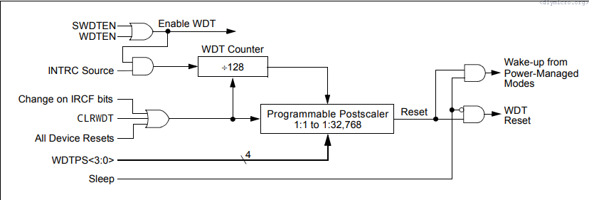
If the chip in the sleep mode, watchdog will pull it out of the chip, while in the active mode it will completely reset it. The basic unit for one watchdog tick is 4ms, I settled the postcaler to 256, which gives 1 second watchdog period. I’ve put the sleep command inside of single sensor polling when I have 4s waiting time. It technically can be set to larger amount of time, but I was worried about post processes after waking the chip up:
I was kind of counting – for this ~4s period we have 3s with 2.5mA and then pretty much 0 (well should be 60uA). We can perform some really rough hand estimations of the RMS value and get like 2.16mA. I could have gone further and try to experiment watchdog period, but was kind of lazy.
After this I was sprinkling CLRWDT() commands through the code to not let program to reset where it should not be reset. I also did change the threshold for touched sensor to higher value (like 50) and reduced amount of pulses in a single batch, so sensor touch feels more natural.