At some point of time we built together with my daughter a simple mechanical elevator and then I had an idea – why not to make it motorized and have just couple of buttons and have a bit of experience with the H bridges and motors.

At some point of time we built together with my daughter a simple mechanical elevator and then I had an idea – why not to make it motorized and have just couple of buttons and have a bit of experience with the H bridges and motors.
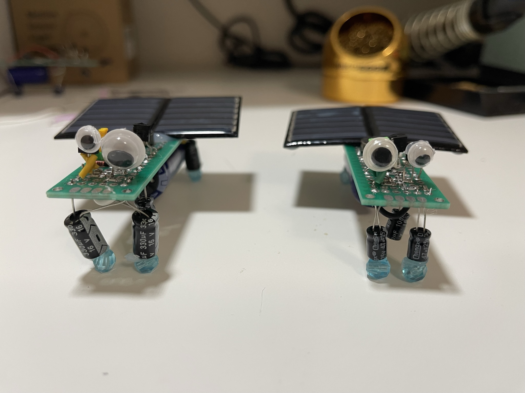
Recently my daughter brought a journal from the local library. There was a bug bot my daughter said she wanted to make and it was dead simple. There was just one problem with that – I did not get how it could work at all – there was just a solar cell and the vibration motor just connected directly. The motor needs like constant 60mA of current, how is that possible that a tiny solar cell can provide that?
So I ordered cheap motors and cheap solar cells from a you-know-the-name website and guess what, it did not work.
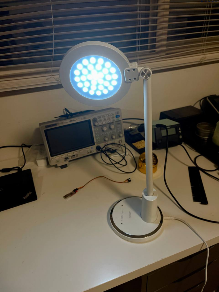
At some point I got the cheap lamp from amazon, it costs about 12$ but worked surprisingly well till some point… Looking under the hood revealed some ugly solutions:
The project which unfortunately was not finished due to my relocation to other country and taking such a project with me certainly would raise some question at the security control 🙂
A situation in place was the next – my half done amplifier was working already 3 years just proving the statement “there last longing device is a temporary one”. It was kind of fine – but it consumes an energy. In a fact a solid chunk of the energy – it is class A amplifier. At some point in time I started to think – why to not switch on/off the amplifier in dependence on the signal presence.

The situation: there are two bathrooms, which have fans controlled manually.
The goal:
Let’s go.
Continue readingInitially, I was thinking to not put this stuff to a separate article, but then decided to do it in a separate one, since it looked like it worth to do this.
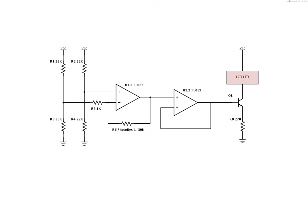
I have added a small additional pcb for my diy amp project, which is dedicated to detect the drop of VDD voltage level and saving the data to EEPROM at reaching of the certain threshold. All how I described here, I used the built-in comparator from PIC168f877a.

It is a pity that I have not added this feature to the main pcb, so now all solutions looks unaesthetic.
Continue readingThe code of the DIY amplifier has grown much, it is harder and harder to debug it and keep in the order. So first of all I have added the audioprocessor part to the existing code, not much to discuss it is already been considered. Only one thing – I added the display LCD functions instead of the uart menu. I still want to have the USB connectivity so I can take control over amp from the PC. The plan is to use the FT232 with the virtual com port. Of coarse, it would be a nicer way to use PIC18 with USB on-board, but at the moment of time I did not have the experience with it, and now, when I actually have it – I would still go the virtual com path, usb has too much of the hustle to implement and handle nicely, besides it is not free for use as usual usb.
Continue readingAnother movement towards finishing my “pet” project – an audio amplifier with remote control.