The diy devboard for pic16f628a

At that point of time, I did not have a lot of possibilities to buy any commercial development board, so I had to make my own
devborad

I wanted to make a small board, not those huge with everything you can imagine, and, perhaps, never going to use. A 3d model shows what I wanted and what I made: 4 buttons + 4 LED hanging on the PORTB. There is also one button and one LED for PORTA. Everything can be disconnected from the microcontroller using the dip switch.

Continue reading

Pic Lab, PIC16, Experiment #9, The timer2 module

The goal: the same as previous, to get the 1KHz pulse.

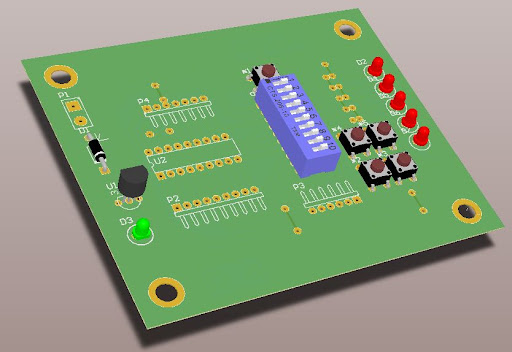
What do we have: PIC16f628a, the simple devboard + proteus.

For this particular uC the timer2 module is another 8bits timer, which has some peculiarities.

timer2, a picture borrowed from the mikroe resourse
Continue reading

Pic Lab, PIC16, Experiment #8, The timer1 module

The goal: to get 1 Hz pulses.

What do we have: PIC16f628a, a handmade devboard, and proteus

Continuing to learn pic microcontrollers, and the timer1 is the next module in our way. Usually, this is a 16bit timer, so it allows to have a larger time frame.

timer1 block diagram, pic16f628a datasheet
Continue reading

Pic Lab, PIC16, Experiment #4: 7 segment display

It was 2012 year, I was just starting to learn how to work with the PIC microcontrollers, so the code is far away from optimal.

uC: PIC16F628a

Compiler: Hi-TECH PICC

Goal: To connect 7 segment indicator and display numbers from 0 to 9

7 segment indicator connection
Continue reading

PIC Lab, PIC16, Experiment #3: Timer TMR0

uC: PIC16F628a

Compiler: Hi-TECH PICC

Goal: To make pulses with frequency 5Hz

Timer TMR0 module frequently used in many applications, it has next useful options:

  • 8 bits counter/timer
  • Internal/external oscillator for pulses counting
  • An interrupt is generated after overflow

In that experiment we will make it without using interruptions.

Timer TMR0 module (from datasheet)
Continue reading